
Stretch the Geometry of a Part
Advanced Face Modeling Package
General
- You can stretch a volume either along the selected line or in the direction of the selected line between two selected faces.
- If the part does not have a line indicating the direction of stretch, which also determines the start and end of the stretch, model it before the operation.
- Instead of a line, the part may have two faces or auxiliary planes that define the beginning and end of the stretch.
- Model parts outside the stretch area remain stationary (at the start) or move with the stretch (at the end).
Usage examples
- To stretch a volume without history (imported volume) because there are no other ways to do it.
- To stretch a part if handling previous historical features is difficult.
- When a shape is desired for a part that is not otherwise readily available.
Stretch
- Select the ribbon bar function Part | Deformation |
 Stretch or
- Import | Deformation | Stretch.
- Import | Deformation |
- Select a line from the model to indicate the rotation axis.
- For example, the line of the guide curve or the edge line of the model face.
 If you point to two planes (step 3) that are parallel, you do not need to select a line indicating the direction of stretching.
- If there is no line parallel to the stretch direction in the model, abort the function and first model a control line that indicates the direction of the stretch and its start and end points.
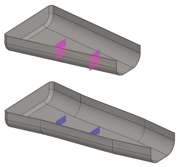
- Select the stretch distance by selecting two faces or auxiliary planes.
- This is optional if you selected a line (step 2) whose endpoints are valid as the start and end of the stretch.
- The endpoints of the line guiding the direction of stretching are used to indicate the beginning and end of the stretching if no faces or auxiliary planes are selected.
- Select Confirm.
- The program opens the Stretch dialog box.
- Define the stretch data in the dialog box.
- Enter the stretch in the Distance field.
- Enter the formula or variable in the Formula field, if you want to control the stretch using a dimension table.
- Select the stretch direction.
- In: The part gets shorter.
- Out: The part gets longer.
- Click Apply to see what the part will look like with the values you enter.
- Edit the data in the dialog box, if necessary.
- Select OK.
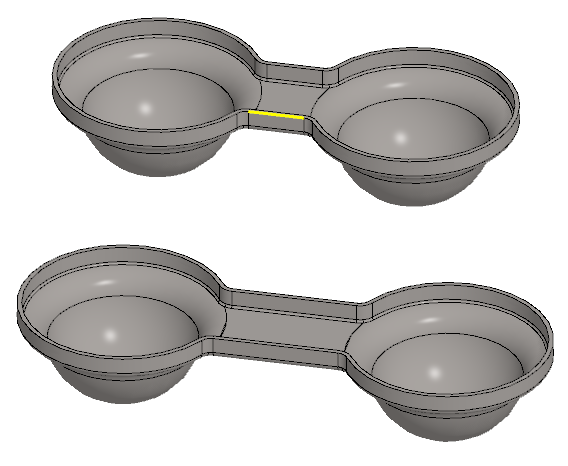
Example 1:
Stretching is controlled by one line:
- The line guiding the stretch (guide curve) extends to the center of the cups.
- Without the Stretch function, modeling the shape below would be significantly more laborious.
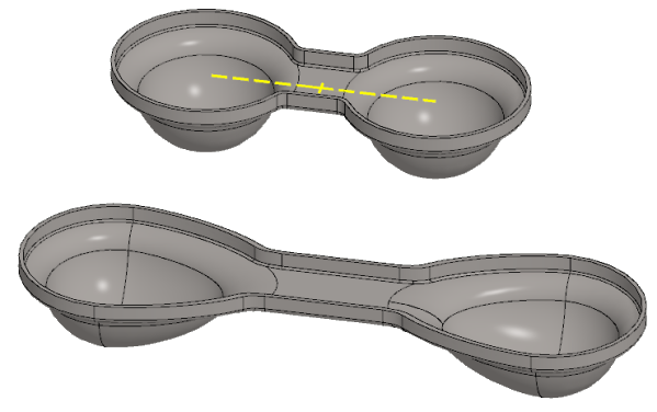
Example 2:
Stretching is controlled by a line and two auxiliary planes:
- The line guiding the direction of stretching is the same length as the part.
- Two auxiliary planes have been modeled for the stretch area.
- Stretching is done by selecting a line and two auxiliary planes and entering the stretch.
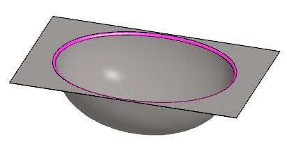
Example 3:
The hemispherical basin is stretched into a half-ellipsoid-shaped basin.
- Roundings should be done after stretching.
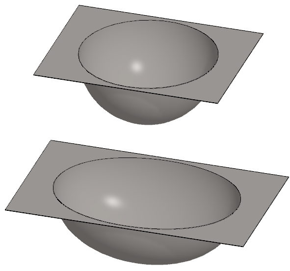
- For stretching, both end faces are selected from the plate.
Roundings and remarks on the model.
- Note that the stretch makes the faces different in thickness, depending on the direction of the stretch relative to the face.
- If this difference in surface thickness is important and it is a volume made of sheet metal, then finally use the Tangential Offset function.
- In the case of a deep-drawn volume, that uniform thickness is irrelevant, since the deep-drawn part is not uniform in every respect.
Note:
- Edit the feature by selecting it from the feature tree and clicking Edit.
- The Stretch Data dialog box opens.
- Edit the values and the selections.