
Add a Library Feature to a Sheet-Metal Part
Sheet-Metal Design
General
- The library features added by the software supplier related to sheet metal can be found in the library Features > Sheet_metal and can be found in the browser when using the function.
- Uses for sheet metal libraries:
- Opening: Features should only be used in the function
 Trim a Corner
 - Box: You can use this feature as the first feature of a new part model.
- Punching: Features remove material, i.e. punch the sheet metal.
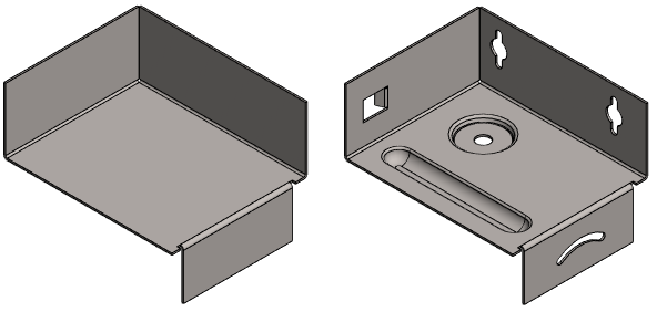
- Special_forming: Features are added to the sheet metal to shape it. The feature includes both boss and cutout geometry.
- Flanges: Features can be used to add flange features.
- Ducting: You can use this feature as the first feature of a new part model.
- Opening: Features should only be used in the function
Paste Library Feature
- Select the function:
- Part | Library Feature |
 Boss or
 - Part | Library Feature |
 Cut or
 - From the context-sensitive menu: Library Feature >
 Boss or
 - From the context-sensitive menu: Library Feature >
 Cutout.
 - The program opens the browser.
- Part | Library Feature |
- Select the library feature in the browser.
- Features > Sheet_metal
- The program opens the dimension table related to the feature.
- Enter the dimensions of the feature in the dimension table.
- Select OK.
- If the feature is the first feature of the part model (retrieved from the library Box or Ducting), choose how to add the feature.
- Part: The entire history of the feature is shown in the feature tree, and you can edit each feature separately and, if necessary, delete features using the feature tree.
- Feature: The feature appears as a single feature and you can only edit it using the dimension table of the feature.
- The geometry is added to the origin of the part model.
- If the feature is added to a sheet metal model that already has geometry (retrieved from the Punching, Special_forming or Flanges library), click the location of the library feature on the desired surface.
- The program switches to sketching mode.
- Locate the geometry of the feature with the sketch constraints.
- Accept the sketch and exit the sketching mode
- Select the function Sketch | Return |
 OK or
OK or - Select the context-sensitive function
 OK.
OK.
- Select the function Sketch | Return |
Note: You can edit the library feature of a sheet-metal part using the dimension table values by first selecting the face formed by the feature on the part, and then selecting the Edit Operation function. A fast way is to double-click a face formed by the feature in the model, or double-click the symbol in the feature tree of the part.