
Trim a Corner
Sheet-Metal Design
General
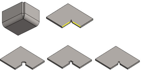
- With the function, the corner created as a result of modeling in the 3D-flattened part is shaped into the desired shape.
- If the sheet blank is cut with a laser machine, it is often desired that there are no sharp corners in the toolpath of the laser, but that the toolpath mainly consists of a rounded chain of lines. In this case, the laser does not "burn a hole" at the points where it stops for a moment when changing direction.
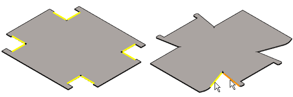
- If the angles of all corners of the sheet are the same, the program will automatically select all corners when you start the function.
- Left image: The angles of the corners are the same size, so the program has selected all the corners as soon as the function is started.
- Right image: Some corner angles have two different sizes, so you have to select the corner lines by clicking.
- The program tries to automatically calculate the minimum dimensions of the corner trimming tool to the extent that rebending is successful.
- However, the program cannot take into account a situation where the corners have different angles.
- In this case, you should first trim all the corners and later modify the trims with too small dimensions to at least the size that the program suggested for the dimensions of the tool in the largest angle.
- You can trim several corners at once, in which case the program uses the same tool and the same values for all corners.
- If you use a library feature as a corner trimming tool, select only corners of the same size to trim at a time, because the program varies the corner of the features to the same angle, so it is not suitable for all corners.
Starting point
- The model is a sheet metal part.
- The part is flattened.
Trim Corners
- Select the ribbon bar function Sheet metal part | Tools |
 Trim Corner
- The program opens the dialog box Corner Trim Properties.
- If the corners on the surface are the same size, the program selects all the corners automatically, and you can go to step 4 in the instructions.
- If the surface has corners of different sizes, click the lines of the corners.
- Click the corner lines in pairs, i.e. two lines from each corner.
- Finish selecting the corners to be trimmed with the Confirm function. (Confirm = V key, middle mouse button or the context-sensitive function
 OK.
OK. - Select the trim method if it differs from the default, i.e. the circle.
- Circle (is the default).
- Square.
- Feature. (Dimensionally variable library feature).
- If you selected circle or square as the trim method, complete the data in the Corner Trim Properties dialog box.
- If you want, you can enter a value greater than the minimum value calculated by the program.
- Enter a variable and/or formula, if you want to control the tool values by using a dimension table.
- Go to step 7 in the instructions
- If you selected Feature as the trim method, click
 Select.
- The program opens the library feature browser.
- Select the desired trimming feature, for example, from the Features/Sheet_metal/Opening folder by double-clicking the feature.
- Select OK.
- The program opens the dimension table related to the feature.
- The program completes minimum dimensions for the feature.
- If necessary, enter values greater than the minimum dimensions for the feature.
- Select OK.
- The program adds tools that are varied and positioned in corners to the model and switches to sketching mode.
- Visually check that the tools are the right size and are positioned sensibly.
- Select OK.
Trim the selected corners
- Select lines in pairs from the corners to trim.
- Select the context-sensitive function
 Trim Corner.
- The program opens the dialog box Corner Trim Properties.
- Continue as above, steps 4...7.
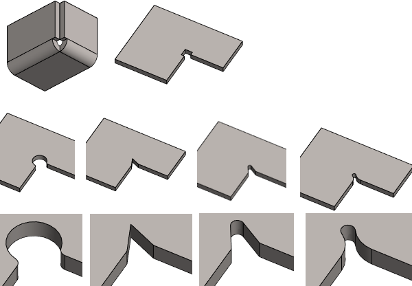
Examples of corner trims created with features
- In the features, r and r2 values greater than the minimum values have been used to make the shape more visible.
- In the top row, the initial situation in case form and 3D-flattened.
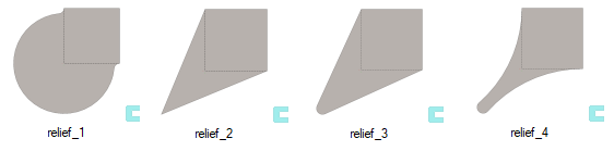
- Features from left to right in order relief_1, relief_2, relief_3 and relief_4
Note:
- You can modify the size of a library feature or change a library feature to another library feature when you select the feature in the part’s feature tree under Corner trim and the Edit operation function.