
Model a New Machining Feature
General
Machining geometry is created in two ways:
- When you perform the operation
 Boss
Boss Extrude for a sketch, select the option
  Make Tool.
 - Model the part, and select
 Properties and Tool, so that the geometry of the part will be a tool in its entirety.
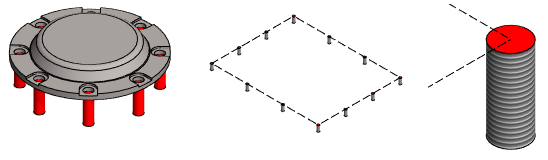
- The machining geometry is drawn in red color.
- Note that the thread part of the machining thread feature is drawn like a normal thread.
Steps when a part has regular geometry and a machining feature.
- Start a new part model
- File >
 New.
New. - Select
 Part.
Part. - Enter the archive data
- File >
- Sketch the geometry of the part and perform the necessary boss and cutout extrusions and other features.
- Note that the origin point of the first sketch of the part acts as a locating point.
- However, it is worth adding a grip to a library feature. Add a Grip Point
- Sketch the machining feature's geometry.
- If you are only modeling a machining feature without boss geometry, first model the part as finished, and then change its properties to a tool (see the General section).
- Accept the sketch.
- From the ribbon bar with the function Sketch | Return |
 OK or
OK or - Select the context-sensitive function
 OK.
OK.
- From the ribbon bar with the function Sketch | Return |
- Perform the operation Boss Extrude for the sketch and select the option
 Tool.
Tool. - If necessary, edit the machining feature with a bevel or rounding, for example.
- If necessary, add a dimension table for the model.
- With a dimension table, you can control both the regular geometry and the geometry of the machining tool.
- For more details, see Edit the Dimension Table of a Part Model
 When creating a sheet metal machining feature, enter the letter t in the Formula field of the feature to have the sheet thickness always automatically checked from the model.
- If you create a sheet machining feature, change Sheet Metal as the part's type by selecting the context-sensitive function
 Properties and selecting Sheet Metal in the Type section.
 - When the part model is finished, save it by selecting the context-sensitive function
 Save To Library > As Feature.
 - Select the machining feature's execution order in the Choose tool execution order dialog box.
- Select Tool geometry first if you want the machining feature to remove the material first and then add the feature geometry.
- Select Additive geometry first if you want to add the geometry of the feature first and then remove the machining feature from the part.
- Select Tool geometry stays as tool geometry if you want the feature tool to remain a tool when it is added to a part model.
- Select
- Select OK.
- Select the folder to which you wish to save the feature, and name the file. If necessary, create a new folder.
- Select Save.