
Edit the Dimension Table of a Part Model
General
- You can edit the values of all variables associated with the part.
- You can enter descriptions for the variables in the dimension table.
- You can add rows to the dimension table that describe allowed or recommended sizes.
Prerequisites for the function
- A numerical value and a variable name in the Formula field have been assigned to the dimension constraint in the sketch and/or
- You can define a variable for the dimension when adding the dimension constraint, or later by selecting the dimension constraint for editing.
- Drawing a Model Sketch
- Adding Constraints to a Sketch
- Contents of the Formula Field
- A numeric value has been entered for a sketch-based feature, for example extrusion or revolution, and a variable name has been entered in the Formula field or
- You can define the variable when adding a feature or afterwards when you select the feature and the context-sensitive Edit Operation function.
- You can select a feature either from the feature tree or by selecting one surface from the feature.
- The other features of the part model, for example rounding, draft or shelling, are given a numerical value and the name of the variable in the Formula field.
Edit the dimension table and add dimension table rows to it
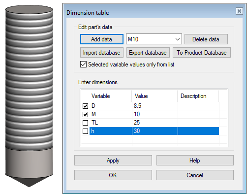
- Once the model is finished, select the context-sensitive function: Dimension Table.
- Fill in the information in the Description column if the variable name is not descriptive enough.
- Enter the label of the dimension table row in the top field.
- Based on this label, you can select the desired size.
- The content of the label should describe the data of the dimension table row, because the size of the feature or component stored in the feature or component library is selected based on this label when adding a feature or component.
- Enter the desired variable values in the Value column.
- See dialog box information: Dimension Table Data Dialog Box
- Save the row by clicking the Add Data button.
- Repeat steps 4 and 5 until all the sizes you need are entered.
- If you have a large number of sizes, you might want to enter the data in Excel. See the Export Database section below.
- If you want the user to be able to select only the sizes that are stored in the dimension table, select
 Selected variable values only from the list.
- If, however, the user is allowed to change the value of a variable, leave the Variable column checkbox
 unchecked in that row.
 - In the example image above, the pre-drill (D) and thread (M) variables of the threaded hole feature can only be selected from the list, but the drilling depth (h) and threading depth (TL) can be given.
- If, however, the user is allowed to change the value of a variable, leave the Variable column checkbox
- Select OK.
- The program varies the part to the dimensions that are currently in the dimension table.
- Save the part as a library feature or component, if necessary.
Example
A dimension table of a part model, from which the editing of the variable values is blocked for length and width, but the thickness value can be entered.

When a part model is saved in the feature or component library and when a feature is added to a part model or a component is added to an assembly, the dimension table looks like this:
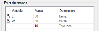
- The image of the lock symbolizes the values of the locked variables, which can only be changed by selecting another row of the dimension table.
- In the figure, the thickness (t) value can be freely entered.
Note:
- You can edit the dimension table of a part later, for example by adding variables after the part has been saved. In order for the data to be updated to the part model in an assembly, you must separately define the creation of a dimension table while the parts are being saved. Add the keyword set.dimensiontable.saving= 1 in the user/Setup file of the Vertex folder.