
Connect Areas
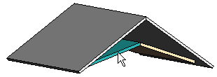
You can connect two horizontal structure areas to each other so that they will always be parallel and at the specified distance from each other. For example, you can connect a sloping ceiling to a roof. One of the areas is defined as movable and the other one fixed. If the parallelity or distance of the structures are not fulfilled after you have made changes to the building model, the program will move the movable structure.
 If the movable area forms a joint with
another area (for example, a ridge joint between roof slopes), connect both areas to a fixed
area in order to prevent the joints from becoming undone.
If the movable area forms a joint with
another area (for example, a ridge joint between roof slopes), connect both areas to a fixed
area in order to prevent the joints from becoming undone.
- Select Modeling | Connection |
 Joint
Joint  Plane
Structure
Plane
Structure
 Connect
Parallel.
Connect
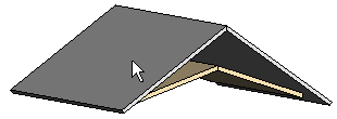
Parallel. - Select the movable area.
If the layers have been expanded,
select a layer, too.
- Select the fixed area.
- Select the next movable area.
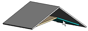
- Select the next fixed area.

- Once you have selected all movable-fixed pairs, select the Confirm function.
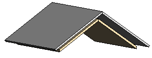
- Enter the distance between the reference lines of the areas in the text window. Enter a
positive value when the movable area is below the fixed area, and a negative value when the
movable area is above the fixed area.
 Note
Note
- The reference line of an area is on the top or bottom face of the packed basic volume. You can determine the location of the reference line by opening the area properties for viewing in a dialog box.
- You can remove a connection by editing the constraints of the area.
- Alternatively, you can select the function from the context-sensitive menu. Select the
movable area, right-click to open the context-sensitive menu, and select
 Connect Parallel.