Edit a Model by Moving Points
General
- You can stretch or shrink the length of the model or its parts by selecting points to stretch.
- However, the program will not, for example, stretch a planar surface into a spline surface by moving one corner point.
- If you try to move points where the type of surfaces would change (plane > spline, etc.), then instead of moving, the program moves all points of the model, i.e. the model moves from one place to another.
- Selecting one (planar surface) point means the same as if you had selected all edge points of the planar surface.
- Note that points on concentric circles always move together.
- If necessary, you can select all its points from the surface by pointing to the surface and then selecting the context-sensitive function Select surface points.
Usage examples
- The function is mainly intended for stretching the profile-like parts in an assembly.
- You can use the function to stretch or move an imported part model or its details, as they do not include modeling history that could be modified to make the necessary changes.
Move the points selected from a part model
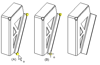
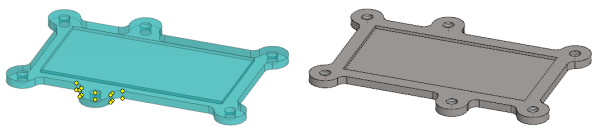
- Select the points to be moved from the part (A).
- Hold down the Ctrl key when you select several points from a part.
- You can select all points of a surface by clicking the surface and then selecting the context-sensitive function Select surface points
- Select the context-sensitive function .
- The program opens the dialog box Move Points.
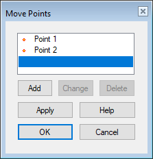
- The program opens the dialog box Move Points.
- Edit the element selections in the dialog box.
- View, change or delete the selected points by clicking the buttons. Select a point from the list and click the button.
- You can add a point by clicking the Add button.
- Preview by clicking the Apply button in the dialog box.
- Confirm the selections.
- Select a reference point (B), in relation to which you want to specify the offset.
- Specify the offset or enter the offset as a distance value relative to the reference point.
- The offset can have a positive or negative value.
Selecting the Points Using Area Selection
- This works both in a part model and in an assembly model.
- You cannot use this function to move points of link parts in an assembly model.
- Select the context-sensitive function .
- Select the area inside which the points to be moved are located.
- Finish selecting points with the Confirm function. (Confirm = V key, middle mouse button or the context-sensitive function
 OK.)
OK.)- The program marks the points to be moved.
- Click a reference point.
- Click or enter the offset.
- If necessary, you can use the directional locks: U, I and O, if you click the offset using the cursor.
- The program asks if you accept the offset.
- Answer Yes, if you accept the offset.
Example 1
- The part has been stretched in length by moving points.
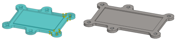
Example 2
- The detail of the part has been moved from one place to another by moving points.
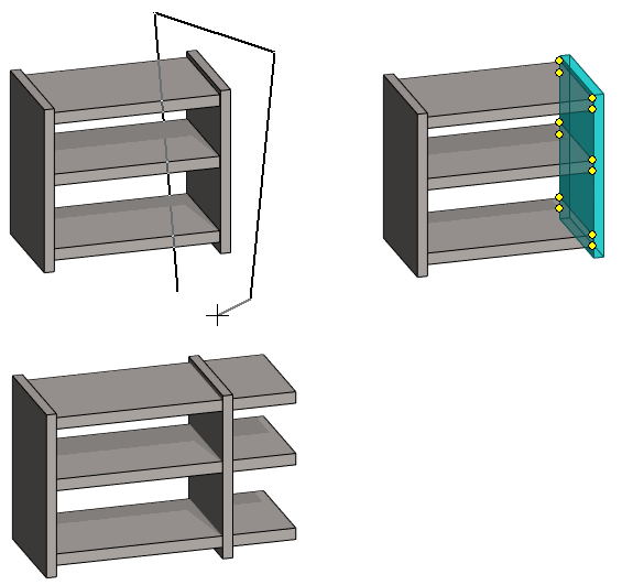
Example 3
- The length of the shelves of the shelf consisting of local parts has been changed by stretching the points.
- In the upper left image, the area selection points (4 pcs.) are visible.