Divide a Part with a Cutout Extrude/Revolve Feature
You can use a cutout feature to divide one part into two. A new part is created from the cutout volume.
A local assembly with local parts is created.
- The original part is converted into an assembly. It retains its original label.
- The remaining geometry of the original part is saved as a local assembly part with the name
 PART.
PART. - The material (volume) cut out from the part is saved as a local assembly part, which you can name.
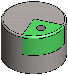
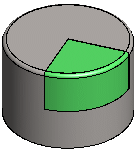
Our example uses a sheet-metal part. A new part is created when the part is divided, Part_1 (green).
 |
 |
 Divide the part with a feature as the last step after otherwise completing the part geometry. If you edit the sketch of the cutout feature or the feature data after dividing the part, the new part will not be updated with the changes.
Do as follows:
- Open the part you wish to divide in two in the working window. The part to be divided can be a normal part or a sheet-metal part.

- Add a new sketch to the part.
- Divide the part by sketching a closed polyline (division line).
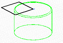
- Select Confirm.
- Select either of the following as the operation to be performed on the sketch:
 Delete and
  Extrude
- Delete and Revolve
- If you want to create a part of the cut out material, select

 New Part.
 - Click OK.
- Fill in the properties of the new part:
- Name the part.
- Define the offset width, in mm.
- Click OK.
- Define the properties of a feature. For example, define the length of an extrusion feature.
- Click OK.

Note:
- You can rename a local part in the part properties or save it in the archive.
- You can continue modeling of the new part in the normal way.