
Split Surfaces with a Line
Select the Split Line operation. Use the split line to divide the single or several surfaces to the surfaces.
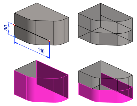
Define a split line in the volume.
- Select a surface or auxiliary plane from the part.
- Select the context-sensitive function New sketch to surface.
- Draw the line in sketching mode.
- Select the context-sensitive function
 OK.
OK. - Select

 Split Line as the operation.
 - In the section Selected elements 1, click the right mouse button and select the context-sensitive function.
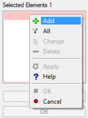
- Select Faces individually in the model by selecting Add or select All.
- Select Confirm.
- If you select a wrong face, you can either change it and select a new one, or remove the selection by first selecting the face from the list and then clicking the Change or Delete button in the dialog box.
- Select OK.
Example: A surface is divided by a line chain
- An open line chain is sketched on the surface of the part.
- A line chain can begin and end on the edge line of the surface or it can extend beyond the extremes of the part.
- If the line/line chain does not extend up to the edge lines of the selected surface, the surface cannot be divided.

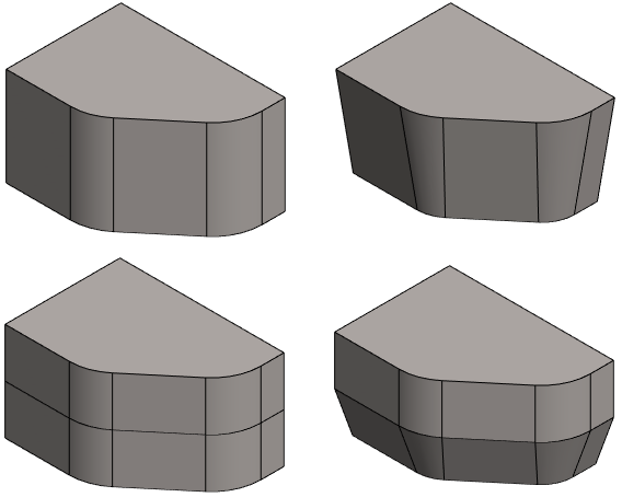
Example: A split line is added for a draft
- The surfaces are first divided in two.
- For the reference face of the draft, an auxiliary plane has been added to the split line.
- The draft is add on the surfaces below the split line.
-
- See how to create a draft: Create a Draft
Note:
- Edit the sketch of the split line, when you select the feature from the feature, and the context-sensitive function Edit Sketch. You can edit the selection of the split faces by selecting the context-sensitive function Edit Operation.
- There may be problems during drafting, preventing the creation of the draft. You can then make drafting easier by using split lines to divide the drafted face into parts.