
Bend a Part
Advanced Face Modeling Package
General
- You can bend the model according to the specified radius or angle around a particular bending axis in relation to the desired reference face.
- You can bend a part even if it is not a sheet metal type.
- Note, however, that the elongation typical of a sheet metal is not taken into account in this bending.
- The deflection axis must be modeled before bending.
Bend a Part
- Select the ribbon bar function Part | Deformation |
 Bend or
- Import | Deformation Bend.
- The program opens the Bend dialog box.
- Bend Part Data
- Import | Deformation
- Click the planar surface and the rotation axis that define the direction of bending and the point of bending (either the beginning or the center).
- The part bends outwards or inwards from the selected surface.
- The rotation axis does not have to be located on the clicked planar surface.
- The rotation axis is projected on the planar surface.
- Select Confirm. (Confirm = V key, middle mouse button or the context-sensitive function
 OK.)
OK.)- The program adds the reference face and the rotation axis to the dialog box.
- After this, you can enter or select other necessary data.
- Define the bend data in the dialog box.
- Bend angle and formula, if necessary.
- Bend radius and formula, if necessary.
- Click the Side button to select the bending side:
- The left side bends from the bending line.
- The right side bends from the bending line.
- Both sides bend. That is, the bend line is in the middle of the bend.
- Click the Direction button to select the bending direction:
- Bends outwards from the reference face.
- Bends inwards from the reference face.
- Limit the bend region, if necessary.
- Select faces or lines you want to move.
 Select the lines from the side of the bend.
- If you have set the bend to occur on both sides, the limiting area has no effect.
- Select Confirm to add the selected elements to the Bend Range list.
- Click Apply to see what the part will look like with the values you enter.
- Edit the data in the dialog box, if necessary.
- Select OK.
From the context-sensitive menu
- Select a planar face, which has diverging end points projected to the plane.
- Select the context-sensitive function
 Bend.
Bend. - Continue as above, steps 4...6.
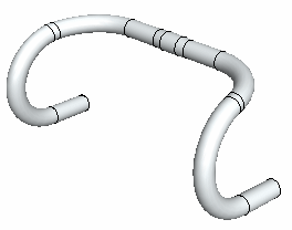
Example: Handlebar
You can create a handlebar by bending a pipe part two times and then mirroring it.
- In addition to the geometry of the pipe (length 650mm, and diameter 24mm), two guide lines have been modeled in the part, which are used to indicate the beginning of the bend.
- Default planes of the part model are used as reference faces.
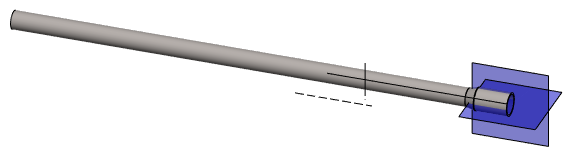
- First bend: Reference face, Rotation axis, Direction, angle 90° and radius 40.
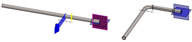
- Second bend: Reference face, Rotation axis, Direction, angle 180° and radius 100.

- Mirroring so that the geometry of the original is preserved. The end face of the pipe acts as the mirror plane.
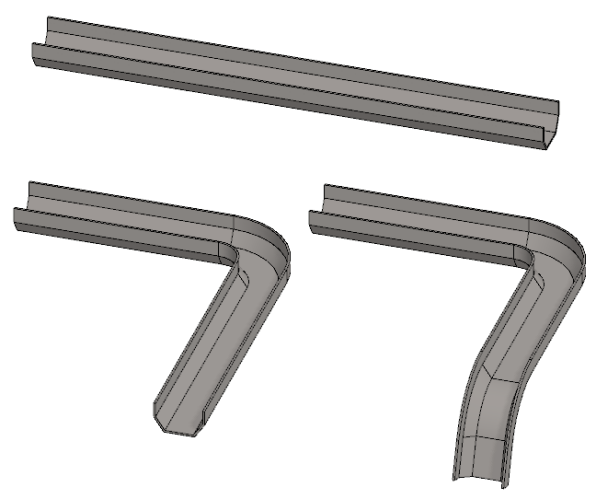
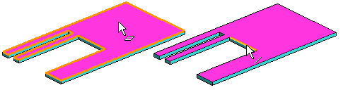
Example 2. The bend region is limited
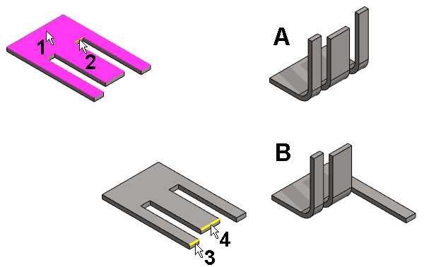
- The planar surface (1) has been selected.
- The rotation axis (2) has been selected.
- The bend angle of 90 ° and the bend radius (10) has been entered.
- The result is shown in the figure A.
- Two lines (3 and 4) has been selected to specify the bend region.
- The result is shown in the figure B.
Note:
- Edit the feature by selecting it from the feature tree and clicking Edit.
- The Bend dialog box opens.
- Edit the values and the selections.