
Twist a Part around the Axis
Advanced Face Modeling Package
General
- You can twist a part around the rotation axis you select.
- The line indicates the direction and location of the rotation axis, and the start and end points of the twist area.
- You can also indicate the faces that limit the twist area, so that the line only determines the location of the rotation axis.
- The preview planes at the ends of the line (parallel to the plane normal) indicate the range of the model that will be twisted.
- Model parts outside the twist area remain stationary (at the start) or twist with the rotation (at the end).
- If you do not click the line that points the rotation axis, but only click the limiting faces, the program calculates the rotation axis, but the result can be unexpected.
Usage examples
- Modeling of spiral objects (conveyor screws, ice drills) and modeling of objects made by twisting (fire poker etc.).

- The figure shows two guide lines in the middle of the part, which are used to indicate the rotation axis and the beginning and end of the twist.
- Each line is twisted separately.
Twist a Part
- Select the ribbon bar function Part | Deformation |
 Twist or
- Import | Deformation | Twist.
- Import | Deformation |
- Select a line from the model to indicate the rotation axis.
- If there is no line parallel to the rotation axis in the model, abort the function and first model a control line that indicates the position of the rotation axis and its start and end points.
- Select the faces or planes limiting the twist area from the model.
- This is optional if you selected a line (step 2) whose endpoints are valid as the start and end of the twist.
- Define the data in the Twist dialog box.
- Enter the angle value.
- Select the twist direction.
- In
- Out

- In
- Click Apply to see what the part will look like with the values you enter.
- Edit the data in the dialog box, if necessary.
- Select OK.
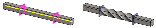
Example 1:
- The rotation axis is the length of the entire part and is located in the middle of the part. The twist angle is 360°.

Example 2:
- In addition to the rotation axis, the faces limiting the twist are selected. The twist angle is 360°.
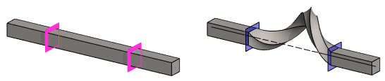
Example 3:
- The rotation axis is not selected at all.
- The faces limiting the twist are selected. The twist angle is 360°.
- The program calculates the rotation axis, and the result may be unexpected.
Example 4:
- The rotation axis is outside the part. The twist angle is 360°.

Example 5:
- The edge line of part is selected as the rotation axis. The twist angle is 360°.

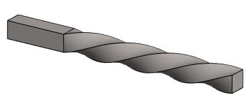
Example 6:
Wood drill bit.
- Two guide lines have been modeled on the drill bit body, one for twist in the body and the other at the tip.
- The model could also have one rotation axis and three auxiliary planes used to define the beginning and end of the twist.
- The twist angle in the body 1440° (= 4* 360°) and in the tip 360°.

Example 8:
Left: The twist required when modeling a meat grinder screw. The axis has not yet been modeled for the part.
Right: A screw modeled for an ice drill.
- Note that the shape of the cross-section is retained, regardless of whether the part is cut at any point after the twist in the direction of the normal plane of the rotation axis.
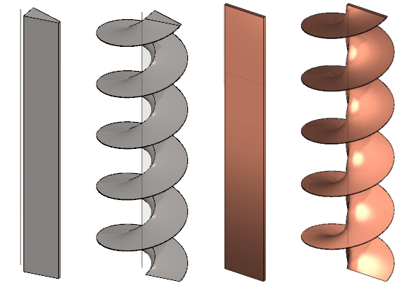
Note that the shape of the ice drill modeled with the twist function is thinner at the outer edge than at the inner edge.
- Figure on the left.

- If a uniform thickness is desired for the part, use the Tangential Offset function after the twist.
- Figure on the right.
- Tangential Offset
Note:
- Edit the feature by selecting it from the feature tree and clicking Edit.
- The Twist dialog box opens.
- Edit the values and the selections.