
Automatic Constraints and Dimensioning
This function can be used to define the constraint and dimension types to be added to a model sketch automatically. Define the data in the dialog box.
Dialog Box Options
- General settings
- Defines how dimensions and constraints are added automatically to a sketch.
- Constraints
- Defines the constraint types to be added to a sketch. You can select or deselect a constraint type by clicking the checkbox. You can select or deselect all dimensions by clicking the Select all button. The available constraint types are: Concentric, Perpendicular, Parallel, Coincident, Tangential and Equal Radius.Note: The Symmetry, Equal Distance and Midpoint constraints cannot be added automatically.
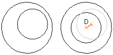
- Linear tolerance
- Defines the linear tolerance (D) with which the constraint will be realized.
- Angle tolerance
- Defines the angle tolerance (a) with which the constraint will be realized. The tolerance area is 0 < a < 45 degrees.

- Dimensioning
- Defines the dimension types to be added to a sketch. You can select or deselect a dimension type by clicking the checkbox. You can select or deselect all dimensions by clicking the Select all button. The available dimension types are: Radius and Diameter, Angle, and Distance. Automatic dimensioning uses Diameter Dimensioning for circles.