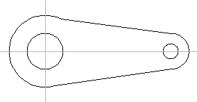
Draw the sketch as close to its final shape as possible. Select the Automatic constraints function. Select Constrain all in the dialog box.
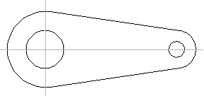
Define the center points of the arcs in the origin of the sketching coordinate system and in the axis point. Select the automatic constraint: Coincident, linear tolerance for example, 0.1, as the center points of the arcs have been set in the origin of the sketching coordinate system and in the axis point. Select OK. The Coincident constraint will be displayed in the part's feature tree. You can view the constraint using the feature tree functions.
Define tangency by selecting the automatic constraint: Tangential, linear tolerance for example, 2. Confirm the data. Select OK.
Make the arcs concentric by selecting the automatic constraint: Concentric, linear tolerance for example, 0.1.
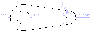
Define automatic dimensioning: Radius and Distance. The following dimensions will be added automatically.
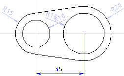
Edit the dimension constraints and add the Distance constraint between the center points of the circles. Notice the changed color of the dimensions.
The sketch is defined. You can edit the constraints.