
Spiral Settings
Specify the feature settings in the dialog box. Do either of the following:
- Edit the spiral data by double clicking the the feature symbol in the part feature tree.
- Open the spiral data with the context-sensitive function Edit operation.
Familiarize yourself with the features by following the links below.
- Axis Line
- Delete reference geometry
- Spiral spinning direction
- Pitch
- Formula
- Threads
- Start radius
- End radius
- Start exceeding
- End exceeding
- Start point
- Variable pitch at begin / end
- Apply
Axis Line
Select the axis line visible to help locating the spiral. Its length is equal to the height of the spiral. If the spiral is coincident with a face, the length of the center line is equal to the average of the radius, and its center point is in the middle of the spiral.
| Top of Page |
Delete reference geometry
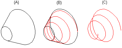
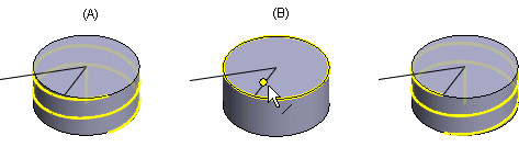
Hide the reference geometry by selecting the function. If the model contains other geometry in addition to the reference geometry used in modeling the spiral, this function will hide it as well. The guide curve and cross sections are not hidden. The reference geometry is usually hidden when modeling springs.
For example, the spiral is automatically added to a conical reference geometry (A), which is visible (B), or hidden (C).
| Top of Page |
Spiral spinning direction
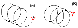
Defines whether the spiral begins Clockwise (A) or Counter-clockwise (B). Select either of the following:
| Top of Page |
Pitch
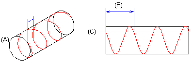
Defines the thread's advance in the direction of an axis in millimeters per rotation (360°).
The spiral is added to a cylindrical surface (A). The thread advance, pitch (B) per rotation, is illustrated in the parallel projection. The axis of the thread (B) has been drawn in the picture for clarity.
| Top of Page |
Formula
Define the feature's variable.
| Top of Page |
Threads
Defines the number of threads with an advance in the direction of an axis, compare to Pitch.
- Fill in either pitch or number of threads in the spiral properties. The second value is calculated automatically.
| Top of Page |
Start radius
Specify the radius of the spiral beginning. The default is zero. Specify the radius value in relation to the center point of the spiral.
| Top of Page |
End radius
Specify the radius of the spiral end. The default is zero. Specify the radius value in relation to the center point of the spiral.
Example: The spiral's radius value is zero in the picture A and greater than zero in picture B.
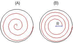
- Either numeric value of the radius must be greater than 0 so that the spiral can be modeled.
| Top of Page |
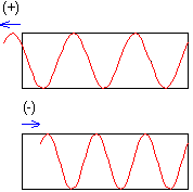
Start exeeding
Defines the offset of the spiral's start point in relation to the selected geometry. If the start point is exceeded, the offset is positive (+). If the spiral starts before the start point, the offset is negative (-). If necessary, you can select a point from the spiral reference geometry by first clicking the Click button.
If you want to model a spiral in order to indicate reference geometry offset, you can select a guide curve and select the point from the guide curve (see Start point).
| Top of Page |
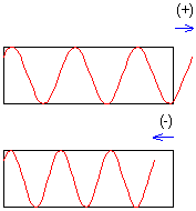
End exeeding
Defines the offset of the spiral's start point in relation to the selected geometry. If the start point is exceeded, the offset is positive (+). If the spiral ends before the end point, the offset is negative (-). If necessary, you can select a point from the spiral reference geometry by first clicking the Click button.
| Top of Page |
Start point
Drafting a spiral starts in the origin of the cylinder. When you sketch a cylinder or click a radius point of the cylinder in the sketch, the selected point is the origin. The spiral always starts at the top of the extruded cylinder.
If necessary, you can select a new start point position from the reference geometry.

If you want to model a spiral in order to indicate the reference geometry start point, you can select a guide curve and position the spiral at the guide curve point (A). The guide curve can also extend outside the planar face. Click the Click button and click a point (B) on the guide curve line to set it as the start point of the spiral. The point is projected to the border line of the planar face and defined as the start point of the spiral.
| Top of Page |
Variable pitch at begin / end
Define a variable pitch at begin or end or in both of the spiral. Drag a slide control to select steepness of the pitch. The maximum of the variable pitch at the begin and end together is 100% and the software adjusts the other slider automatically.
| Top of Page |
Apply
Preview by clicking the Apply button. If necessary, you can still edit the feature data before accepting the data.
| Top of Page |