Spiral Guide Curve
Create a spring or spiral by selecting one of the following:
- Using an auxiliary surface: Create a spiral guide curve to the cylinder, cone, or planar surface. The border line of a planar surface must be a circle.
- Without an auxiliary surface: Create one straight reference line to be a guide curve.
You add later a cross section to the guide curve, after which you use the guide curve and the cross section to create sweep features that either add or remove matter. This way for example thread grooves on cylinder and cone surfaces, and cylindrical and conical springs are possible.
Create a spiral to a guide curve:
- First model the reference geometry to help in the creation of the spiral. For example, create a cylinder or straight line and make it a guide curve.Note: Drafting a spiral starts in the origin of the cylinder. When you sketch a cylinder or click a radius point of the cylinder in the sketch, the selected point is the origin.
- Select the context-sensitive function
 Add Spiral of the guide curve.
 - Define the spiral properties in the dialog box, so that the feature is modeled.
- Confirm the selections.
Example: Create a spiral without an auxiliary plane.
Create a straight line and make it a guide curve. Select the context-sensitive function Add Spiral of the guide curve. Define the spiral settings and confirm.

Example: Create a spiral using an auxiliary plane.
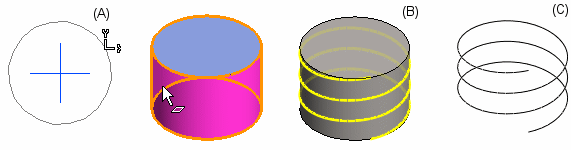
Create a sketch (A) and extrude a guide curve of it. In the sketch, the selected radius point is the origin of the cylinder. If you intend to model a thread groove on the face of a cylindrical part, the reference geometry is retained (B). If you model a spring, the reference geometry is hidden (C).
The spiral always starts at the top of the extruded cylinder.
Add spiral to a part model
- Open the part model in the working window.
 Browse - Archives
 - Select a cylinder, cone, or a planar surface.
The border line of a planar surface must be a circle. Note, drafting a spiral starts in the origin of the cylinder.
- Select the context-sensitive function Add Spiral.
- Define the spiral settings.
- Confirm the selections.
- You can create a cylindrical or a conical spring or a thread groove by adding a cross section to the spiral guide curve and creating a boss or cutout sweep for them.
- Edit the spiral data by double clicking the the feature symbol in the part feature tree.
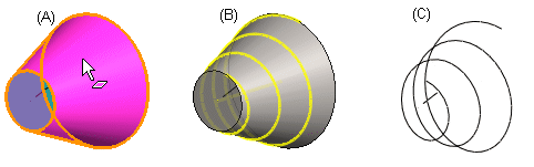
Example: Conical spiral using an auxiliary surface
Add a spiral on a conical face (A) so that the reference geometry is either retained (B) or hidden (C).
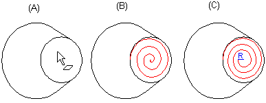
Example: Planar spiral
Add a spiral on a circular planar face (A). Define the center point of the face as the end point of the spiral, with the radius value being 0 (B) or radius > 0 (C).