
Create a Draft
General
- Draft is used in castings to make it easier to remove the part from the molds. Draft refers to the skewness of the mold surfaces in the direction in which the mold is removed.
- Draft can be made on one or more surfaces at once. 1)
- By default, draft is done for all surfaces tangential to the selected surface at once, so it is better to add drafts before adding small corner rounds.
- Draft is made in relation to the reference surface 2). On the reference surface, the size of the part does not change. A suitable reference surface is:
- A planar face of a part.
- Cross section.
- Plane.
- Draft can be additive or subtractive, in relation to the draft surface.
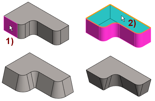
- Top left image: The surface to be draft is selected.
- Top right image: The reference plane is selected.
- Bottom left image: The draft is additive.
- Bottom right image: The draft is subtractive.
Create draft
- Select the single or several drafted surface from the model.
- Select the context-sensitive function
 Draft.
 - Select the part's surface, auxiliary plane or cross-section as the reference plane.
- Define the draft data.
- Draft angle or angles if the reference plane is in the "center" of the surface to be draft.
- The direction of the draft
 Add or Remove.
- Preview by clicking the Apply button. If necessary, you can still edit the feature data.
- Select OK.
Example when several surfaces have been selected for draft
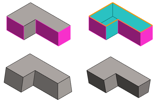
- Top left image: The surfaces to be draft have been selected.
- Top right image: The reference plane has been selected.
- Bottom left image: The draft is additive.
- Bottom right image: The draft is subtractive.
Note:
- You get a draft in the extruded shape when you enter a value in the Draft angle field.