
Relocate a Feature
General
- You can relocate a sketch-based feature, i.e. constrain the sketch to another surface, for example, or enter offsets and rotations for the sketch plane.
- You can use relocating to precisely position a cross section on a guide curve.
- By relocating, you can fix a situation where, for example, the sketch has detached from a surface that has been removed as a result of a change to a previous history phase of the part.
- A feature detached from geometry is highlighted in red in the feature tree of the part.
Relocate a feature as follows
- Select a sketch or a plane from the feature tree of the part.
- Select the context-sensitive function Relocate.
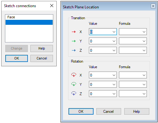
- The program opens the dialog box Connect a Sketch.
- This dialog box is skipped if the sketch is constrained to default planes.
- Change the constraining plane, line, or points, if necessary.
- Select the surface, line, and point to which the sketch is constrained from the list.
- Click Change.
- Select a new corresponding element. See details Sketch Connection Data.
- Select OK.
- The program opens the dialog box Sketch Plane Location.
- Enter the necessary offset and rotations.
- For more details, see: Sketch Plane Location Data
- Select OK.
Relocating a feature selected from geometry
- Select one face from the feature.
- Select the context-sensitive function Relocate.
- Continue as above, steps 3..6.
Note:
- Attaching a sketch positions the sketch in relation to its origin. You can position the geometry of a sketch in relation to its origin either by adding geometric constraints or by editing the existing constraints.
- Relocate a rounding or a bevel by selecting the feature for editing. The dialog box can be used to locate the feature on another line.