
Round Feature Data
General
- The dialog box is related to the part model function
 Round or the context-sensitive function Add Round/Bevel > Round or Add Round/Bevel > Single Edge Round.
 - The program lists all edges, and defaults to them the previously entered radius as the rounding radius.
- By default, all rows are selected, so values are entered for each line at the same time.
- The rounding can be changed to a bevel and vice versa.
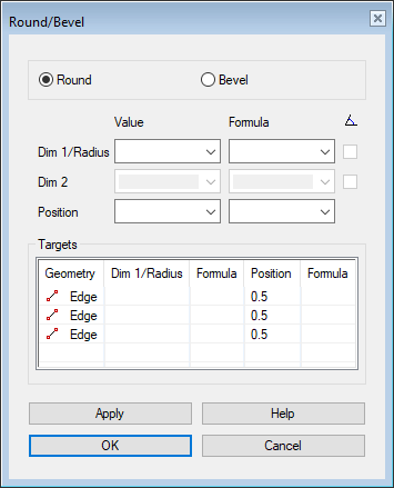
Dialog Box Options
 Round
Round- Sets the dialog box options for entering rounding.
- Deactivates the Dim 2 fields and the

 angle input selection.
- Deactivates the Dim 2 fields and the
- Bevel
- Sets the dialog box options for entering bevel.
- Activates the Dim 2 fields and the angle input selection.
- Activates the Dim 2 fields and the
- Dim 1/Radius - Value
- Enter a radius. The smallest allowed radius value is 0. The value of the radius is shown in the part and is illustrated with green color when the value is editable.

- Dim 1/Radius - Formula
- Enter a formula or variable, if you want to control the size of the rounding with a dimension table.
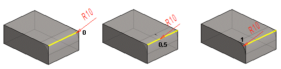
- Position - Value
- Enter the position of the radius on the line in the Position field.
- Position - Formula
- Enter a formula or variable, if you want to control the position of the rounding with a dimension table.
- Add a new line to the list of rounded lines
- Add a line to the rounding by pressing the Ctrl key and select the line.
- Targets list
- In the Targets list, you can select one or more rows and enter values, formulas and positions for them.
- If you selected more than one row, all the selected rows will have the same value you entered.
- Apply
- Preview the model by clicking the Apply button. This will show you how the model would look if you confirmed the feature data by clicking OK. If necessary, you can still edit the feature data.
- Remember to click the Apply button whenever you have edited values different from other rows for a single row.
- Unattached
- The lines/points of a failed feature, no longer existing in the geometry of the part, are indicated with an asterisk (*) and Line0 marking. Select the element (*) to be attached from the list and then a new line/point while holding down Ctrl.
 Click the OK button only when you want the feature to be modeled using the values entered.