
Offset Faces
Advanced Face Modeling Package
General
- You can add or remove material that is created when a parallel offset is applied to selected surfaces.
- A usage example is an imported model that does not include the modeling history of the part model that could be modified to make the necessary changes.
- The function can also be used for a part modeled with Vertex that includes history.
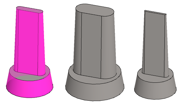
- On the left is the original part from which two offset faces have been selected.
- In the middle is the part on which the Out going face offset is made.
- On the right is the part on which the In going face offset is made.
Offset Faces
- Select the ribbon bar function Part | Faces |
 Offset Faces or
- Import | Faces | Offset Faces.
- Import | Faces |
- Select the face or faces that are to be moved.
- Select Confirm. (Confirm = V key, middle mouse button or the context-sensitive function
 OK)
OK)- The program marks the faces to be moved in the model with red and
- opens the dialog box Offset Face in which the faces to be moved are listed.
- Define the face offset data in the dialog box.
- Enter the offset in the Value field.
- Enter a formula or variable, if you want to control the offset with a dimension table.
- Select the direction of the offset:
- In: The part "shrinks" for the selected face.
- Out: The part expands for the selected face.
- Click Apply to see what the part will look like with the values you enter.
- Edit the data in the dialog box, if necessary.
- Select OK.
Create an offset on the faces selected in the model
- Select a face or faces:
- Hold down the Ctrl key if you select more than one face.
- Select the context-sensitive function
 Faces> Offset.
- The program opens the Offset Face dialog box.
- Continue as above, steps 4...6.
Example 1:
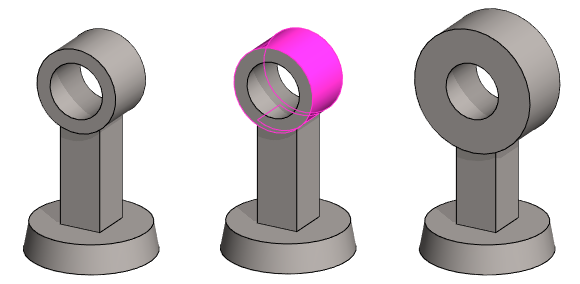
- One face is selected from a part.
Example 2:
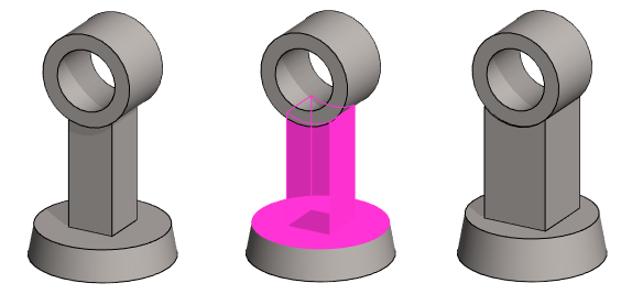
- Several faces are selected from a part.
Example 3:
The size of the groove on a face is modified.
- Note that all faces, including roundings, must be selected.

- On the left, offset is done by selecting In.
- On the right, offset is done by selecting Out..
Note:
- Edit the feature by selecting it from the feature tree and clicking Edit.
- The Offset Face Data dialog box opens.
- Edit the values and the selections.