
Move or Rotate Parts Using Grip Points
The grip points allow you to move a part in the direction of its own major axis or rotate a part around its own major axes.
Grip points in general
When you select a part, the grip points will appear.
- By default, only the grip points according to which the part or subassembly is free to move or rotate are displayed.
- Solving the degree of freedom of the grip points takes its own time and is slower the heavier the assembly, i.e. the more parts in the assembly and the constraints between them.
- We do not recommend the use of grip points, for example, in large plant model configurations.
Adjust the degree of freedom of the grip points
In an assembly, first click its main symbol in the feature tree  and then select the contextual function
  Properties.
and then select the contextual function Properties.- Select
 Solve free directions of under-defined, if you want to solve the degrees of freedom of the grip points.
 - If the grip points are not solved, all grip points will be displayed in the part, even if the part is fixed.
You can also change the default program settings so that the degrees of freedom in a new assembly are either solved or not solved.
- File >
 System Preferences > Edit > Administrator’s View
 - The keyword can be found in the 3d/Assembly settings group.
Values of the keyword analyse_underdefined_at_solve
- By default, there is no value, so the program solves the degrees of freedom of the grip point.
- 1 = free directions are solved.
- 0 = free directions are not solved.
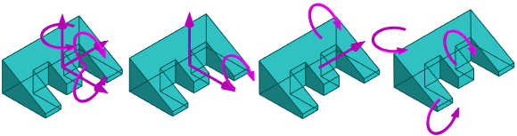
Moving or rotating a part using solved grip points

- Select a part or a subassembly.
- The program uses the grip points to show the degrees of freedom of the part
- Select the moving or rotating grip point and hold down the mouse selection button
- Move or rotate the part to a new location, either
- By dragging the part into place and releasing the mouse selection button or
- By dragging the part in the right direction and entering the offset or rotation from the keyboard.
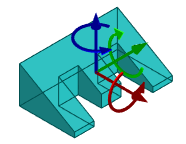
Moving a part using a general grip point
- Note that the general grip point only appears if the degrees of freedom of the grip points are not solved.

Note that this drag also releases the fixed part, but does not override the part restricting constraints.
- Select a part or a subassembly.
- The program draws on the grip point all the axes and their rotations, even if the part is fixed or its position is determined by the assembly constraints.
- Select the moving or rotating grip point and hold down the mouse selection button
- Move or rotate the part to a new location, either
- By dragging the part into place and releasing the mouse selection button or
- By dragging the part in the right direction and entering the offset or rotation from the keyboard.
Note: However, the part will not move or rotate if the constraints of the assembly restrict the displacement or rotation in the direction of the selected grip point.
Alternative: Drag a part in the drawing plane
You can drag a part in the drawing plane as follows.
- Move the cursor over the part you want to move.
- Click and hold the mouse selection button.
- Drag the part to a new location.
- Release the mouse selection button.