
Add Flange
Sheet-Metal Design
General
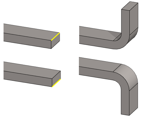
- With the function, you can add a flange feature to the edge of the thin sheet, which consists of a cylindrical bending section and a planar section.
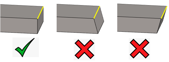
- You can only add a flange on the edge of the sheet that is perpendicular to the flat. In other words, if the sheet is cut diagonally, the addition of the flange feature will not succeed.
- You can bend one or more edges at once, i.e. one flange feature can contain several bends.
- You can enter different feature values for different flanges.
- Selecting the edge determines the initial orientation of the bend that can be changed in the dialog box.
Add Flange
- Select the ribbon bar function Sheet metal part | Tools |
 Add Flange
- The program opens the dialog box Flange Properties.
- Select one or more edges of a sheet, or select a sheet surface.
- Select the edge or the surface of a sheet on the side where you want the sheet to bend.
- By selecting the surface of a sheet, you can select all of its free edges at once.
- Immediately after selecting the edge or surface, the program draws the flange feature based on the information in the dialog box.
- Select the edge or the surface of a sheet on the side where you want the sheet to bend.
- Finish selecting edges with the Confirm function. (Confirm = V key, middle mouse button or the context-sensitive function
 OK.)
OK.)- The program adds the flanges in the dialog box.
- There is no need to stop selecting surfaces, as you can select only one surface at a time.
- With the Add function in the dialog box,, you can also select more surfaces.
- Fill in the data in the Flange Feature Data dialog box.
- First, enter information that applies to all or most of the bends.
- If necessary, define different feature values for different flanges.
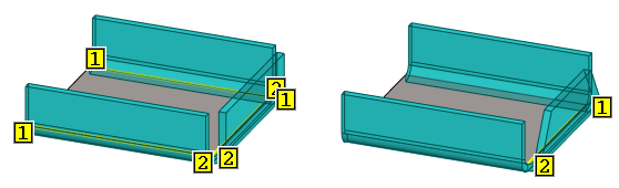
- Click the desired flange in the list. The selected bend is marked in the model with a yellow edge line and boxes 1 and 2 at the ends of the line. In other edges, they are turned off.
- Enter the appropriate values for this flange.
- Select OK.
Add a flange feature to the selected edges of a sheet metal part
- Select one or more edges or one surface of a sheet metal part.
- Hold down the Ctrl key if you select more than one edge.
- You can select another surface only after selecting the context-sensitive function, with Add function in the dialog box.
- Select the context-sensitive function
 Add Flange.
 - Continue as above steps 4… 6.
Note: The stretch calculation method of a sheet metal part is a part property, which you can change by selecting the context-sensitive function  Properties and then the sheet metal part Properties.
Properties and then the sheet metal part Properties.