
Flange Feature Data
Sheet-Metal Design
General
- The dialog box is related to the function
 Add Flange.
 - Add Flange

Dialog Box Options
- Radius R
- Defines the inner radius of the bend.
- The value of the radius of the bending stop or the bending blade should be used as the inner radius.
- Angle A
- Defines the bend angle.
- Length L
- Defines the value of the length.
- Formula
- Defines the dimension’s variable.
 Click
Click- Click the button and select, for example, a length from the sheet-metal part.
-
- You can set the length to a surface or point. You can enter the offset value to the auxiliary menu field
 at the same time.
 - A positive offset value is outwards of the surface and a negative value is inwards to the surface when pointing a surface.
- A positive value continues the bending feature past the point and a negative value leaves the bending feature shorter when pointing a point.
- You can set the length to a surface or point. You can enter the offset value to the auxiliary menu field
- Alternatively, you can click a point outside of the model (B) by selecting the context-sensitive function
 OK or by pressing the middle mouse button to have the length of the sheet be determined by the line drawn by the cursor.
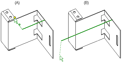
- If the check box is selected, the chosen element is saved in the feature.
 Select
- Click the button to start the definition of a user-defined bend radius. The button is active only when a user-specific fitting has been defined.
- Feature Type
- Defines adding the bend as follows: The red color of the tip image shows the size of the part before adding the bend.

 Add whole bend
 Inside dimension
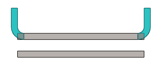
 Outside dimension.
- Cut type
- You can choose the cut type when the type of the feature is
- Inside dimension or
- Outside dimension
- You can select the cut type from the list:
- Only edge
- Edge + corner
- The program cuts the edge and also the corners of the flanges next to it.
- This option only gives the end result according to the image when
 Edge trim is not selected.
- Whole end
- This option only gives the end result according to the image when Edge trim is not selected.
- This option only gives the end result according to the image when
- Only edge
- Additional Dimensions
-
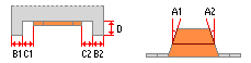
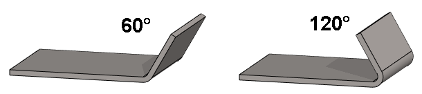
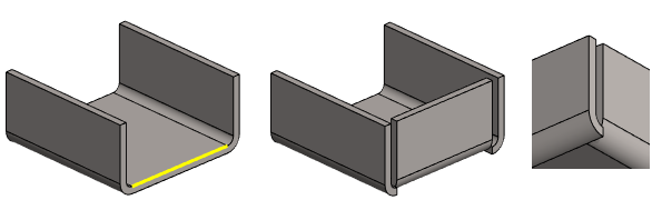
Figure 1: Definitions of the additional dimensions. - Side Angle
- Define the values of the side angles into the Side angle A1 and Side angle A2 fields.
-
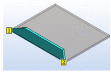
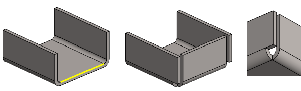
Figure 2: Example: A1 is 60 degrees and A2 is 10 degrees. - Take in
- Define the values of the take ins into the Take in B1 and Take in B2 fields.
-

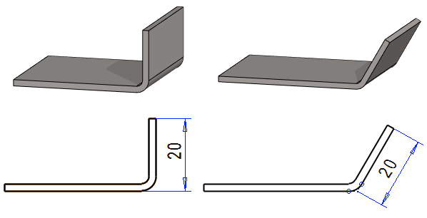
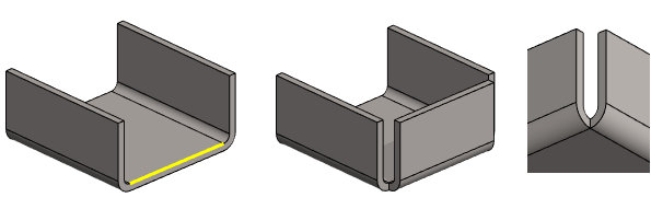
Figure 3: Example: B1 is 30 mm and B2 is 10 mm. - Gap
- Define the values of the gaps into the Gap C1 and Gap C2 fields.
-
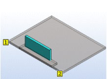
Figure 4: Example: B1 and B2 are 20 mm, C2 is 10 mm and D is 10 mm. - Depth
- Define the depth into the Depth D field.
 Direction
- Change the bending direction by clicking the button

- Edge trim
- Select
 Edge trim if you want to automatically trim edges while adding a flange feature.
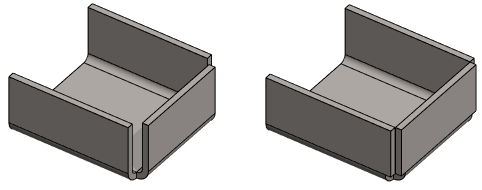
-
- Automatic trimming uses the symmetric trim as a default.
- The software creates two features in the feature tree. Flange and Edge trim. You can edit both features individually.
- You can add selection Edge trim to an existing flange feature, if that specific flange feature is the last phase in the history.
- If other features have already been modeled in the part, add the trimming of the edges as a separate work step.
- Flanges
- A list containing the selected flanges. You can select different feature parameters for each flange.
- Add
- Add new flanges, if necessary.
- Select Add.
- Click the edge, on which you wish to add the flange.
- Change
- If necessary, change the flange to another edge line.
- Select the flange to be changed.
- Select Change.
- Click the edge, on which you wish to add the flange.
- Delete
- Remove any flange, if necessary
- Select the flange to be deleted.
- Select Delete or press the Delete key.