
Split a Large Sheet Surface to Sheet Blanks
Sheet-Metal Design
General
- The split line feature can be used to create sheet splitting for a sheet metal part.
- For example, a tank built from several sheet blanks is modeled as a single model. The sheet seams are displayed for positioning through holes.
- The advantage of this method compared to creating actual welding grooves, for example by a cutout extrusion, is that the model can still be bent and flattened even after the faces have been divided, both during modeling and for the model drawing.
Starting point
- The part is a large cylindrical sheet metal part.
- The part is 3D-flattened.
Create sheet splitting during modeling when the model is flattened as follows:
- Add a new sketch to the face of the part.
- Sketch split lines on the surface of the sheet
- Sketch the lines at the points where there will be welding seams between the bent steel sheets.
- Stop sketching and select an operation.
- Select the ribbon bar function Sketch | Return |
 OK or
OK or - Select the context-sensitive function
 OK.
OK.
- Select the ribbon bar function Sketch | Return |
- Select

 Split Line as the operation.
 - Select the surfaces that you want to split with the line in the Selected Elements 1 section.
- By default, the sketch surface is split.
- You can select all surfaces by selecting the context-sensitive function
 All in the list.
- Select OK.
- Rebend the model back into a 3D model.
Example, a large tank
- The height of the tank is 7m and the diameter is 4.6m.
- The shell of the tank has been cut.
- The shell has been flattened.
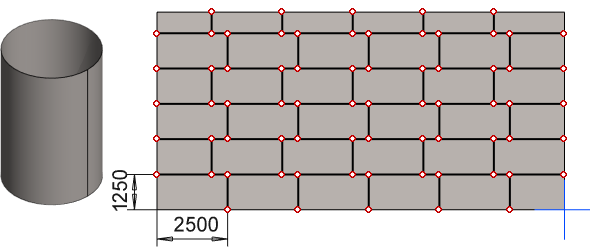
- The size of the steel sheets (1250*2500mm) has been sketched on the surface of the sheet.
- The Split Line has been used as the operation.
- The sheet has been rebent.
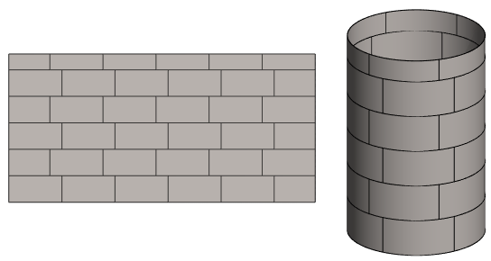
- The lines can be used to outline the placement of the sheet blanks.
- By modifying the sketch of the Split Line, possible tank through-holes can be adjusted to the desired points.
