
Sheet Cut Properties
Sheet-Metal Design
General
- The dialog box is related to the
 Cut Sheet function.
 - Cut a Sheet
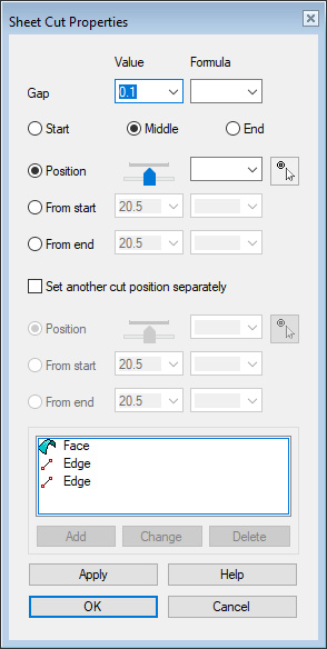
Dialog Box Options
- Gap
- Defines the width of the gap created in cutting.
- Formula
- Defines gap's or position's variable.
- Enter a variable label to control the gap width or position using a dimension table.
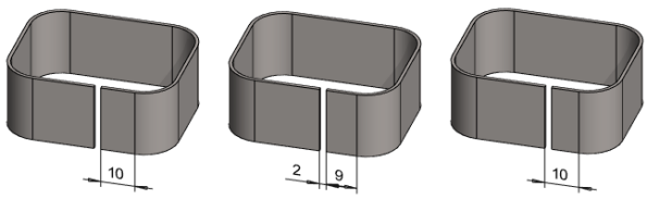
- Start, Middle, End
- Select
 Start
Start- The cut gap starts at the selected position.
- In the above left image, the 2mm gap starts at 10mm from the beginning of the line.
- Select Middle
- The center of the cut gap is at the selected position.
- In the above middle image, the center of the 2mm gap is 10mm from the beginning of the line.
- Select End
- The cut gap ends at the selected position.
- In the above right image, the 2mm gap ends at 10 mm from the beginning of the line.
- Relative Position
- Select Position and define a relative position to the cut with a slide control or formula.
- Click a position
- Click a position in the model by selecting
 .
.- Select the cutting point.
- You can click a point, when you cut a cylindrical or conical surface.
- You can click a point or surface when you cut a planar surface.
- If you click the cut point from the surface, you can use the
 offset function of the auxiliary menu to enter the distance of the cut point from the surface.
 - You can constrain the cut location to the selected surface if you select the "lock" in the auxiliary menu.

- Finish selecting the position with the Confirm function. (Confirm = V key, middle mouse button or the context-sensitive
 OK.
OK.
- Select the cutting point.
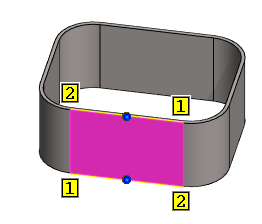
- Exact position: From start, from end
- Select From start to enter the gap position numerically from the the start point of the line.
- Select From end to enter the gap position numerically from the end point of the line.
- The software illustrates the beginning and the end of an edge line with the numbers 1 and 2.
- Set another cut position separately
- For a planar face, you can set another cut position separately on the other edge line. Then the cut is created in a specific direction.
- Select the check box
 Set another cut position separately and define the other cutting point’s position.
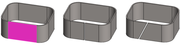
Set another cut position separately and define the other cutting point’s position. - Select the check box
- Elements
- A list of the surface and edge line, or two edge lines that model the feature.
- You can edit the list also with the context-sensitive menu.
- Add
- The option is inactive, as you can cut a sheet from only one surface.
- Change
- Change the cut to another surface, if necessary.
- Select the surface from the list.
- Select Change.
- Click the replacing corner surface.
- Delete
- The option is inactive, as you can cut a sheet from only one surface.
- Apply
- You can see what the part would look like if you accepted the values and options you entered.
- You can change the values and options.