
Fill Gap Data
Advanced Face Modeling Package
General
The dialog box is related to the function
- Part | Faces |
 Fill Gap.
 - Import | Faces | Fill Gap.
- Fill a Gap
- This functionality requires the Advanced Face Modeling Functions option.
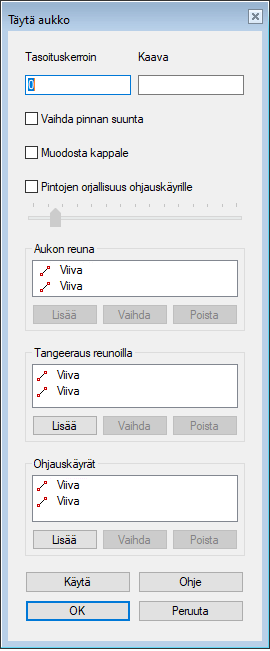
Dialog Box Options
- Flattening
- Try a suitable value.
- The default is 0 (zero).
- The higher the coefficient, the less the face is tangential to adjacent faces and the face becomes "flatter"
- Formula
- Defines the variable of the formula.
- Invert face direction
- Changes the direction of the face to the opposite (reverses the face).
- Make volume
- Creates a volume from a set of faces.
- Faces to be replaced
- The list shows the faces selected to be replaced by tangential faces.
- Maximum number of spans
- The guide curve is followed with default values automatically.
-
- To adjust how closely the face follows the selected guide curve, select
 Maximum number of spans and
- Adjust the value with the slide switch.
- By the small value, the face is more simple, and does not follow the guide curves precisely. A high value creates a more complex face that follows the guide curve more precisely.
- A high value requires more processing power from the computer.
- Edges on Gap
- If you have only selected one line when creating the feature, the list will only include one line. You can select the line chain, in which can also be guide curves.

- Tangency on the edges
- You can indicate lines from the model, which will be tangential to the line chain. Click Add and select the lines.
- Guide Curves
- You can also indicate lines in the mode to function as guide curves.
- Add
- Add a new face to be replaced, a gap edge line, a line that guides the tanging, or a guide curve to the list.
-
- Select Add below the list in question.
- Click one or more elements.
- Select Confirm (Confirm = V key, middle mouse button or the context-sensitive function
 OK)
OK)
- Change
- Change the selected element to another element.
- Select the element to be changed.
- Select Change.
- Click the replacing element.
- Delete
- Remove an element.
- Apply
- Preview the model by clicking the Apply button in the dialog box.
- This will show you how the model would look if you confirmed the feature data by clicking OK.
- If necessary, you can still edit the distances and rotations.