
Add Face Data
General
The dialog box is related to the function
- Part | Faces |
 Add Face.
 - Import | Faces | Add Face.
- Add a Face
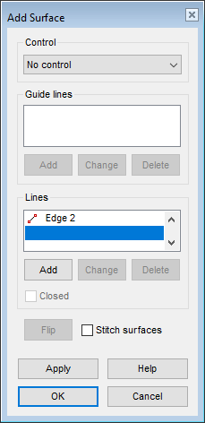
Dialog box options
- Control
- Defines the control from one of the following options. In the samples, both sides of the surfaces have been set visible.
 When you select With guide lines or With virtual guide lines, select the tangential guide curve as follows:
- Select the tangential line chain search by clicking the button:

- Click the first line of the guide curve.
- Confirm selected lines by selecting Confirm. (Confirm = V key, middle mouse button or the context-sensitive function
 OK)
OK)
- Select the tangential line chain search by clicking the button:
- Alternatively, you can individually select each line of the tangential polyline.
- Lines
- Defines the lines between which the surface is modeled.
- The lines that form part of the same polyline are displayed on the list with the same numerical ID, for example Line 1.
- Add
- If necessary, add the edge lines needed to form the surface or the edge lines of the openings on the surface to be added to the plane in the Lines section, or add the guide lines that control the shape of the surface in the Guide lines section.
- Select Add.
- Click the line or lines to be added.
- Select Confirm (Confirm = V key, middle mouse button or the context-sensitive function OK)
- You can add, for example, a hole to the surface by clicking the Add button and clicking the edge line of the hole. The edge line of the hole is a single line (circle) or a polyline which is on the same plane with the surface. You can use the following auxiliary function when selecting a polyline for the hole:
- Click the button to select the search for a line chain in the same plane:
- Click the first line of the polyline.
- Confirm selected lines by selecting Confirm.
- Click the button
- Alternatively, you can individually select each line of the polyline.
- Change
- If necessary, change one of the edge lines needed to form the surface to another one in the Lines section or the guide line that controls the shape of the surface in the Guide lines section.
- Select the line to be changed.
- Select Change.
- Click the replacing line.
- Delete
- If necessary, remove one of the edge lines needed to form a surface in the Lines section or one of the guide lines controlling the shape of the surface in the Guide lines section.
- Select the line to be deleted.
- Select Delete or press the Delete key.
- Stitch surfaces
- Defines the joining of surfaces to each other when adding a new surface.
- If you add new surfaces without stitching surfaces to each other, you have to transform the surface model as a closed volume separately using the function Tangential Offset or To Volume.
- When you stitch surfaces when creating each surface, the creation of the volume is easier.
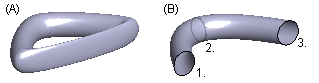
- Closed
- Defines a surface as a closed chain of surfaces (A), when this check box
 Closed is selected.
- This function is available, when a minimum of 3 lines have been selected for the surface.
- The shape is closed by automatically adding the surface between the first and last line.
- If the check box is cleared
 , the surface is added only between the selected lines (B).
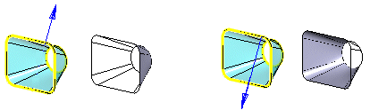
- Direction
- You can reverse the direction of the surface normal by clicking the button Flip. When you choose the direction of the surface normal, you also select which side of the surface is the outside.
- The surfaces are so-called semi-transparent, meaning that the outside of the surface is visible and the inside is invisible.
- In the settings, surfaces can be set to be visible on both sides:
- File > User Preferences > Drawings, Models > View tab > Model group > Show both surface sides always.
- File > User Preferences > Drawings, Models > View tab > Model group >
- Apply
- Preview the model by clicking the Apply button in the dialog box.
- This will show you how the model would look if you confirmed the feature data by clicking OK.
- The preview also displays the surface chirality.
- If necessary, you can still modify the lines and other choices affecting the feature.