
Extrusion Data: Thin Feature
Sheet-Metal Design
Dialog Box Options
- Dimension
- Defines the length, angle, thickness, bend radius or offset value.
- Formula
- Defines the variable for length, angle, thickness, bend radius or offset.
 Length or Angle
- Defines the length of the extrusion. Define the angle of rotation. You can also enter the value as a numerical calculation, such as 360/8. The same calculations are available as in the Formula field. You can also leave the length and angle empty and select

 To Selected Face or
  To Selected Point.
  In Both Directions
- Defines extrusion/revolution of the sketch from the origin of the sketch in both directions with the amount equaling half of the value in the Dimension/Angle field. The length of the extrusion will be the value of the Dimension/Angle field in total.
-
Note: You can change the direction of the extrusion by clicking the In Both Directions icon.
- To Selected Face
- Defines extrusion/revolve to a face clicked from the model. If
 In Both Directions is selected, select a surface for both directions. You can select more than one face from both sides of the sketch plane. The only limitation is that the faces must be connected to each other. The selected faces are displayed in the dialog box, where you can change or delete the faces. Select a face from the list, and select the context-sensitive Change or Delete.
 - To Selected Point
- Defines extrusion/revolve in the direction of the sketch plane normal to a point selected from the model. If In Both Directions is selected, the extrusion is performed also in the opposite direction of the sketch's plane normal. You can select a single point from both sides of the sketch. You cannot select both points from the same side of the sketch. The selected point or points are displayed in the dialog box, where you can change or delete them. Select a face from the list, and select the context-sensitive Change or Delete.
 Material
- Using the Select button you can select the sheet thickness, density, color and bend allowance. The Material of the Sheet Metal Part
 Sheet Thickness
- Defines the thickness of the sheet. This is a numerical value and it must be greater than 0. You can also enter the value as a numerical calculation, such as 360/8. The same calculations are available as in the Formula field. You can define which direction the thickness is in relation to the sketch line by selecting either
 1st Side or
  2nd Side.
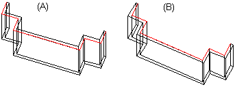
Figure 1: The sketch line is either the inner or outer edge of the sheet.  Bend Radius
- Add a bending radius value or formula for the sheet. The program adds a separate Bend Radius feature on the sheet’s feature tree. You can add a bending radius also as a separate feature. Add Bend Radius
 Offset
- If To Selected Face is selected, you can define a difference between the selected face and the extrusion. A positive offset value takes effect in the direction of the selected face's normal. A negative offset value affects in the direction opposite to the selected face's normal. If In Both Directions is selected, you can specify individual offset values for the selected faces into the fields Offset 1 and Offset 2.
- Selected Elements
- You can later add, change or delete element selections in the fields Selected Elements 1 and Selected Elements 2 (if In Both Directions is selected). For example, select Face in the list and select the context-sensitive function Change.