
Connection Point of a Sketch on a Face
Define the position of the connection point of a sketching face in relation to the selected face in the dialog box.
Dialog Box Options
- Angle
- Defines the position of the connection point as an angle value. The angle value can be between 0 and 360, depending on the size of the face. As you move the cursor along the edge (cylinders and cones), or on a spherical face, and hold down the Alt key, the angle value will change in the dialog box. Enter the exact angle value in the field.
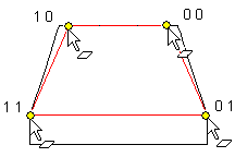
- Relative Position
- The connection point of a sketching face added on a lofting face is defined with two relative position values. The relative position can have values 0-1. With values 0.5 0.5 the connection point will be in the middle of the face. View the relative coordinates on the selected face.
- Formula
- Defines the numeric value as a variable.