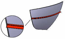
Face Intersection
The surfaces intersection curves is calculated as follows.
- When in the part model is selected at least two intersecting surfaces.
- The face can also be a face that belongs to a cross section or a plane.
- The calculation of an intersection is saved as a separate history step in the feature tree. The intersection is displayed as a guide curve in the model.
- Select at least two intersecting faces in the part model. The face can also be a cross section surface or a plane face.
- Select the context-sensitive function
 Faces>
  Intersection Curve.
 - Define the Curve Properties in the dialog box.
- You can add faces by selecting them from the part model by clicking the Add button.
- If you select
 Delete selected surfaces, only the intersection curves is left visible, and the its calculation used surfaces is removed from the view.
 Faces belonging to sections or planes are not deleted. If you try to delete these surfaces, the calculation of the intersection curve is interrupted, and the software enter the error message.
- Click OK.
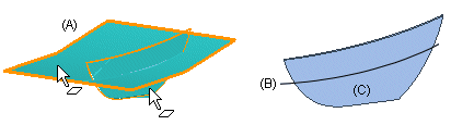
For example, you are create the new part to the the assembly by copying the surface of the other part and add to the surface, which intersect. In the new part, select two faces (A) and calculation of the intersection. If you want to delete the faces selected for calculation, the intersection (B) will remain visible. The reference geometry (C) of the assembly is shown in the background.
You can use the intersection as the guide curve. For example, to add the profile, for example, select the position of the profile cross section from the quide curve.