Draft - Split Line on Drafted Face
A draft can be created for a face of a part divided with a split line. Select the faces and the split line lines one by one. Select as the reference plane the surface, which edge line unite to the drafted surface. The cutout draft effect to the the reference layer normal direction.
- Open a part model in the working window.
 Browse - Archives.
 - Define the drafted surface as follows:
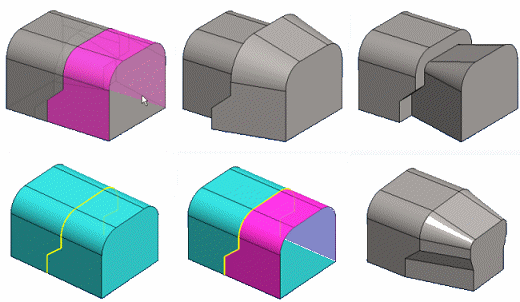
- Select one or more faces to be drafted.
- Select the edge line and split line on the drafted face, from which you want to start the draft. Select the polyline segments one by one. Note that you can use Ctrl when selecting more than one face and line.
- Select the context-sensitive function
 Draft.
 - Select as the reference layer the surface, which edge line unite to the drafted surface.
- Define the draft data.
- If necessary, edit the the drafted surfaces or the reference layer selection by the dialog box functions.
- Click OK.
Note:
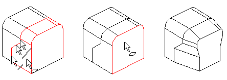
- There may be problems during drafting, preventing the creation of the draft. You can then make drafting easier by using split lines to divide the drafted face into parts.
- For example, Draft by the lines and surfaces.