
Create a Draft in Two Directions
General
- Draft can be done in two directions when an auxiliary plane or a cross-section is selected as the reference plane.
- You can define different draft angles for both sides of the reference plane.
- A negative draft angle value adds the material.

- Select one or more faces to be drafted. (A)
- Select the context-sensitive function
 Draft.
- The program selects all faces tangential to the selected face as faces to be draft.
- Select the reference plane (B):
- Face on an auxiliary plane.
- Face on the cross section.
- Define the draft angle in the dialog box:
- The first angle value determines the draft in the direction of the normal of the reference face, i.e. upwards from the selected face.
- The second angle value determines the draft in the opposite direction of the normal of the same reference face, i.e. downwards from the selected face.
- A positive draft angle value always makes a cutout draft.
- An angle value of 0 is not allowed.
- A negative angle value will create a boss draft.
- If necessary, edit the the drafted surfaces or to the reference layer is elected by the dialog box functions.
- Select OK.
Example 1
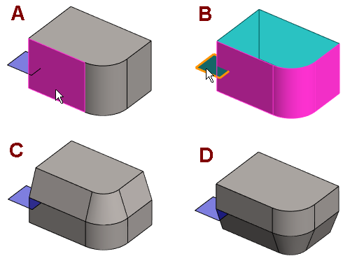
- A: The surface to be draft is selected.
- B: The auxiliary plane is selected as the reference plane.
- C: The upper draft angle is 20° and the lower 0.1° (zero is not valid).
- D: The upper draft angle is 0.1° and the lower one is 20°
Example 2

- A: The surface to be draft and the reference plane have been selected.
- B: The upper draft angle is 30° and the lower one is 10°
- C: The upper draft angle is 30° and the lower one is -10°
- D: Both draft angles are -10°