
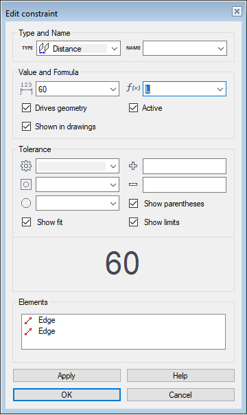
Edit Constraint Dialog Box
Dialog Box Options
- Value
- Defines the value of the distance, angle, or radius, depending on which constraint type you are defining. This is a numerical value and it must be greater than 0. You can also enter the value as a numeric calculation, such as 360/8. The calculations available are the same as those in the Formula field.
- Formula
- Defines a variable or an expression for a distance, angle, or radius. Define the Formula Field
- Drives geometry
- When
 Drives geometry is selected, the constraint will function as a geometric constraint that can edit geometry. You can make a constraint a driven dimension by removing the selection
  Drives geometry. A driven dimension can not edit geometry, but variables or expressions can be assigned for it in the Formula field.Note: Driven dimensions defined in a 3D sketch can be used to create customer deliveries with parametric models (requires Vertex Flow). Read more: Vertex Flow Product Documentation
 - Active
- When Active is selected, the constraint is enabled. You can disable the constraint by removing the selection Active. When a constraint is disabled, you can, for example, drag a line fixed with the constraint in a sketch. You can re-enable the constraint by selecting Active again, and the line that was dragged will return to the position defined by the constraint, for example.
- Shown in drawings
- Defines the sketch dimension visible in the model drawing, when Shown in drawings is selected. You can hide a dimension in the drawing if you remove the Shown in drawings selection from the dimension. Greatest suitability for parts where the shape is determined by a simple planar sketch. For example, flame-cut sheet-metal parts. Add Sketch Dimensions to a Model Drawing
- Tolerance
- You can enter a tolerance for the dimension (distance, angle or radius/diameter). Select one of the following:Select the tolerance type and enter the tolerance values in the fields. You can change the appearance of the dimension by selecting
Tolerance Description None Dimension has no tolerance. Bilateral Upper and lower deviation separately. Symmetric Same deviation in both directions. Fit Shaft or hole fit. Show parentheses, Show fit or Show limits. You can view the appearance of the dimension in the preview box. - Elements
- Defines the elements of the constraint. You can change, add or delete elements.Note: The program will not prevent you from selecting unfit elements. Make sure, that the constraint can be solved for the selected elements.