Circle (Center and Radii Point)
General
- You can sketch circles by clicking the location of the center point and one radius point.
- Instead of clicking the location of the radius point, you can enter the radius of the circle from the keyboard, which automatically adds a diameter constraint to the circle.
- If you point the center of the circle from the origin of the sketch, the endpoint of a line, or the center of another circle, the program automatically adds a concentric condition to the circle with the above element.
- The circle line also has an end point and it comes to the location where you clicked the circle point. However, you cannot snap to this end point, but it is important when you are sketching, for example, a cylinder or cone that is defined as a sheet metal part. The surface of the sheet is "cut" at the point clicked.
- Therefore, when modeling such parts, it is recommended to enter the radius point from the keyboard, in which case it can be made exactly parallel to the X axis, for example. See the example at the end of the page.
Sketch circles
- Select the function Sketch | Lines |
 Circle with Center and Radii Points or
- select the context-sensitive function
 Circle
  Center+Rad.Pnts
- select the context-sensitive function
- If necessary, select the line properties, under Sketch | Style
- Select the center point of the circle.
- Select the radius point of the circle.
- Instead of clicking the point, you can enter the radius of the circle from the keyboard.
- Repeat steps 2 to 4 to continue sketching circles.
- Stop sketching circles
- Select another function or
- Press the middle mouse button or
- Press the Esc key or
- Press the V key (V = Confirm).
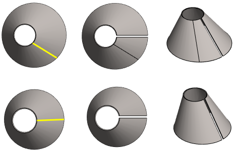
An example of the importance of the radius point location
- In the top row, there is a sheet metal part, the circles of which are sketched by randomly clicking the radius point.
- In the bottom row, there is a sheet metal part, the circles of which are sketched by entering the radius point from the keyboard (in the direction of the X axis).
- The welding gap is modeled in the direction of the X axis, so that no extra break point is visible on the surface of the lower part.