
Linear Feature Pattern
Starting point
- A part has a boss or cutout extrusion or revolution, library feature, swipe or loft that is used as the "parent" feature to form the pattern.
The Ribbon Bar Function
The function allows you to create a pattern of one feature at a time.
- However, you can later add other features to the pattern.
- Select Part | Tools |
 Pattern.
 - Select the surface of the feature from which the pattern is created.
- The program opens the dialog box Feature Pattern Data.
- Define the feature pattern properties in the dialog box.
 Feature Pattern Data
- Select the
 Linear pattern. The most common location choice is Default.
 - See: Linear Pattern Location Options
- Enter the number of members of the pattern in the length and width direction.
- Enter the distance between the members of the pattern or the length of the pattern (length = distance between the first and last member of the pattern).
- Enter the Formula, if you want to control the pattern with a dimension table.
- Select the
- Confirm the data in the dialog box by clicking OK.
- Position the auxiliary geometry sketch that controls the feature.
- If necessary, rotate the auxiliary geometry of the sketch with the functions Rotate left or Rotate right in the auxiliary menu.
- We recommend that you position the auxiliary geometry on a point or line of the feature to be patterned, for example the center of a hole.
- You can change the dimensions of the auxiliary geometry if needed in the sketching mode.
- If necessary, you can remove dimensions from the auxiliary geometry and constrain the part to the geometry with the constraints of the auxiliary geometry.
- Select
 OK.
OK.
The Context-Sensitive Function
This function allows you to select multiple features at once and create a pattern of them all.
- Select the parent feature from a part as follows:
- Select one or more Boss or Cutout operation from the part's feature tree.
- In addition to these, you can choose a rounding or bevel that is connected to the above selected features.
- Select on or more face from the part. Select more than one feature by holding down the Ctrl key while clicking with the left mouse button.
- If you want to create a feature pattern from a rounding or a bevel, you must also include the feature to whose geometry the rounding/bevel has been added.
- Select the context-sensitive function
 Feature Pattern.
 - Steps 3 … 6, as above.
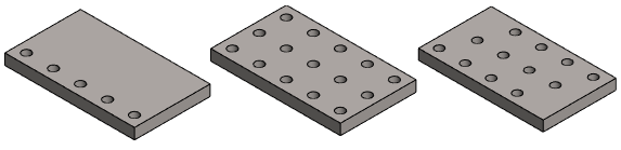
Example of a linear feature pattern
- The number of features in the Length direction is 5.
- The number of features in the Width direction is 3.

Note:
- A feature pattern cannot be created from just a rounding or a bevel. But a rounding or bevel can be added afterwards to an existing feature pattern.
- When more than one feature has been selected for the parent feature, the feature pattern sketch is added to the sketch of the oldest feature in the modeling history of the part. You can edit the feature pattern by selecting the oldest feature Feature Pattern symbol from the feature tree, and the context-sensitive function Edit Pattern.
- When positioning a feature pattern sketch on a line or point of the parent feature using the origin of the sketch as the insertion point, the program will automatically add the Coincident constraint. When you position a line at a center point, the Center point constraint will also be set.
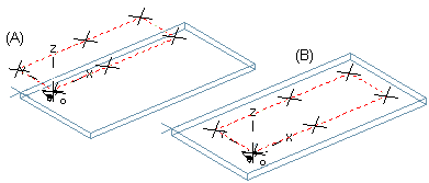
- The position of the parent feature is relevant when adding a feature pattern. The feature pattern will be set in the direction of the positive axes (default). Compare the examples below:
- Add the library feature (A) to the part and create a feature pattern. When you position the feature pattern sketch, some of the features in the feature pattern will be left outside of the part. Rotating the feature pattern does not help.
- Add the library feature (B) to the part and create a feature pattern. The feature pattern will be set as desired.
- Edit the parent feature by double-clicking the feature symbol, and redefining the feature properties. You can select a new size for a library feature from the dimension table. The new feature will also be updated in the feature pattern.
- You can use the dimension table to edit a feature pattern when variables have been defined for the geometric properties of the feature pattern.
Example: Two linear feature patterns form the desired pattern
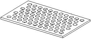
Create a hole pattern using two feature patterns.
- Add the first library feature, use it to create a feature pattern, and position the feature pattern sketch at the center point of the parent feature. Confirm the sketch.

- Add the second library feature, use it to create a feature pattern, and position the feature pattern sketch at the center point of the parent feature. Confirm the sketch.
