Polar Feature Pattern in a Plane
Starting point
- A part has a boss or cutout extrusion or revolution, library feature, swipe or loft that is used as the "parent" feature to form the pattern.
The Ribbon Bar Function
The function allows you to create a pattern of one feature at a time.
- However, you can later add other features to the pattern.
- On the
 tab, in the Tools group, click
  Pattern.
 - Select the surface from the feature, from which you create the pattern.
- Define the feature pattern properties in the dialog box.
 Feature Pattern Data
- Select the
 Polar pattern.
 - Select the direction. The direction only matters if the pattern is not set in a full circle.
- Enter the number of features in the circle.
- Select Angle or Delta and enter a value in degrees.
- Angle: 360= the pattern is placed in a full circle, 180= the pattern is placed in a semicircle.
- Delta is the angle between two features.
- Enter a radius that determines the radius of the arc to be drawn as an auxiliary geometry. Note that this does not define the radius of the polar feature. The default radius is 100
- Select the
- Confirm the data in the dialog box by clicking OK.
- Position the auxiliary geometry sketch that controls the feature
- Note that the selected location determines the center of the polar feature.
- If necessary, rotate the auxiliary geometry of the sketch with the functions Rotate left or Rotate right in the auxiliary menu.
- You can change the dimensions of the auxiliary geometry if needed in the sketching mode.
- If necessary, you can remove dimensions from the auxiliary geometry and constrain the part to the geometry with the constraints of the auxiliary geometry.
- Click
 OK.
OK.
The Context-sensitive Function
This function allows you to select multiple features at once and create a pattern of them all.
- Select the parent feature from a part as follows:
- Select one or mode Boss or Cutout operation from the part's feature tree.
- In addition to these, you can choose a rounding or bevel that is connected to the above selected features.
- Select on or more face from the part. Select more than one feature by holding down the Ctrl key while clicking with the left mouse button.
- If you want to create a feature pattern from a rounding or a bevel, you must also include the feature to whose geometry the rounding/bevel has been added.
- Select the context-sensitive function Feature Pattern.
- Steps 3 … 6, as above.
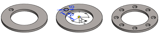
An example of a polar pattern set in a full circle
- The 10mm hole from which the pattern is created is sketched and positioned 40mm away from the center.
- The number of members in the pattern is 8.
- The pattern is set in a full circle, which means that the Angle is 360.
- The radius is 20, which determines only the radius of the auxiliary geometry.
- The pattern is positioned at the center of the flange, so the feature pattern has a diameter of 80 mm
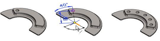
Example of a polar pattern set to an arc
- The hole from which the pattern is created is 50 mm from the center of the shoe.
- The direction of the pattern is Clockwise.
- The number of members in the pattern is 5.
- The pattern is formed in such a way that the distance between the outermost members, or Angle, is 100.
- Radius is 30
- The pattern is positioned at the center of the shoe, so the feature pattern has a radius of 50 mm.
- Note that the arc of the auxiliary geometry does not need to be positioned so that its line points towards the feature to be patterned.