
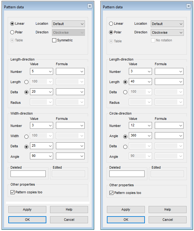
Feature Pattern Data
Select a linear or polar feature pattern. The dialog box adapts to the above choice.
See different feature patterns: Feature Patterns
Dialog Box Options
- Linear
- Defines the feature pattern as linear. Click
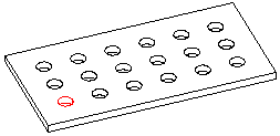
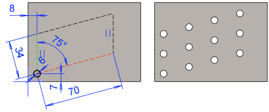
 Linear. You can define a linear feature pattern on a part for example in either one direction or in both the longitudinal and latitudinal direction. For a linear feature pattern, the number of pattern members, length/width or delta, formula and angle are determined.
- Pattern Location
- Defines the insertion plane of a feature pattern. Select one of the following in the list:
Select the positioning method from the drop-down menu.
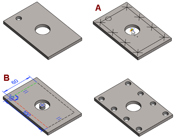
- Symmetric pattern (linear pattern only)
- Select the check box
 Symmetric if you want to create a symmetrical feature pattern.
-
- First, locate the feature to be patterned to the center of symmetry.
- Select the feature to be patterned and the context-sensitive function
 Feature Pattern
 - Select Symmetric
- Position the auxiliary geometry of the pattern at the center of symmetry.
-

- Example 2: The feature is located somewhere other than the center of the symmetry of the pattern.
- Select the feature to be patterned and the context-sensitive function Feature Pattern.
- select: Symmetric.
- Position the auxiliary geometry of the pattern at the center of symmetry (A).
- Position the feature with the coincidence constraint at the center of symmetry (B).
- Select the feature to be patterned and the context-sensitive function
 Polar
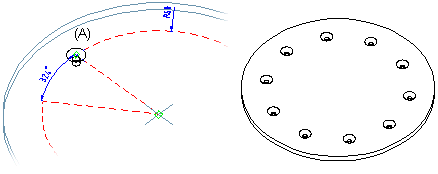
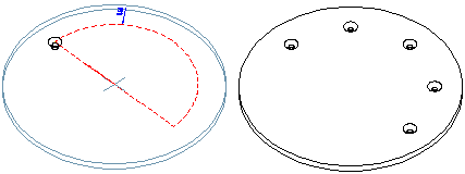
Polar- Defines the feature pattern as polar. Click Polar. For a polar feature pattern, define the number of features, the angle between features and the radius among other things with which the features will be set.
- Direction (polar pattern only)
- Select the pattern’s direction from the drop-down menu. The direction only matters if the pattern is not set in a full circle.
- Clockwise.
- Counterclockwise.
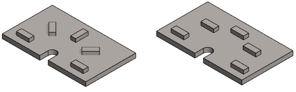
- No rotation (polar pattern only)
- An asymmetric feature will be rotated in a polar feature pattern. You can prevent rotation of a feature by selecting the No rotation check box.
-
- Number
- Defines the number of features to be added to the part. The parent feature, based on which the feature pattern is created, is counted as one of the features in the feature pattern.
- Formula
- Defines a variable for the number, length, width, radius, or angle.
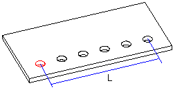
- Length
- Defines the length value (L) in the longitudinal direction at which the features will be set at equal distances. The direction of the positive X axis determines the longitudinal direction on the part (default).
- Check the directions of the axes by pressing the K key, and the cursor changes to a coordinate cursor. A second press of the K key returns the normal cursor.
- If necessary, you can rotate the feature pattern with the auxiliary functions.
- If necessary, you can also rotate the feature pattern using constraints related to auxiliary geometry.

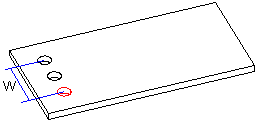
- Width
- Defines the width value (W) in the latitudinal direction at which the features will be set at equal distances. The direction of the positive Y axis determines the latitudinal direction on the part (default).
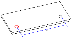
- Scale
- Defines the distance (D) left between the features in either the longitudinal or latitudinal direction. Define a linear pattern to length’s direction: 2 pieces of components, the length is 120.
- Radius
- Defines the radius value of the auxiliary geometry of the polar feature pattern.
- Note that the location of the center point of the auxiliary geometry, relative to the feature to be patterned, determines the radius of the pattern.
- Recommendation: Enter the radius of the polar feature pattern as the radius and position the center point of the pattern in place. After that, position a feature, e.g. the center of the hole with a coincidence constraint in the auxiliary geometry.
- If no radius value is entered, the program will use the default radius value (R=100)
- Angle: Linear Feature Pattern
- Defines the angle of a linear feature pattern. The angle of a symmetrical feature pattern is 90 degrees.


- Angle: Polar Feature Pattern
- Defines the angles at which the features will be set at equal distances. The features will be set clockwise in relation to the parent feature.
- Deleted
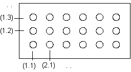
- Defines the features to be deleted from a feature pattern. The position of the features is given as the XY coordinates, entered in parentheses. A period (.) is used to separate the X and Y coordinates. In the Deleted field, you can enter several features to be deleted one after another, for example, (1.1)(1.3). The parent feature is (1.1). You can define the features to be deleted when creating the feature pattern or when editing it.
- Pattern copies too
- This option is displayed in the dialog box if the feature has copies. The selection is also displayed for a feature placed on the cylindrical or conical surface.

