
Dimension Table Data Dialog Box
General
The content of the dialog box depends on the situation in which it opens.
- See different dimension tables: Different Dimension Tables.
Functions for opening the dimension table

Dialog Box Options
- Edit part data
- In the list, select the table ID to be used to edit the part.
- After selecting the table ID, the values defined for the ID will be set for the variables in the phases.
- When you confirm the data, the geometry of the part will change to match the values in the table.
- If the field is empty, no table ID has been defined for the part.
- You can define a table ID by using the Add Data function.
- Add Data
- You can define several table IDs for a part. Each table ID has its own variable values.
- You can create a new table ID by first editing the variables of the part's phases, then entering the table ID and clicking the Add Data button.
- The variable values will be saved as the values of the table ID in question.
- The maximum length of a table ID is 32 characters.
- Naming the Table ID
- Delete Data
- You can delete data from a table by first selecting the table ID to be deleted in the list and then clicking the button.
- Import Database
- The button opens the Windows Open File dialog box, allowing you to load the XML file.
- The content of the file replaces the data in the dimension table if the file format is correct.
 Recommendation: Export the database to Excel and edit it there, and then import it back. In this case, the format of the XML file is basically correct.
- Export Database
- Opens Windows Save File dialog box, in which you can save the dimension table table ID, also the varable data to the XML file.
- The file is opened in the Excel.
- Save the edited file in the same file format.
- Editing a Dimension Table in a XML File
- To Product Database
- Click the button when you want to copy the table IDs defined for a library component into the product database.
- Selected variable values only from the list
- If you select
 Selected variable values only from list, library feature or component is edited by selecting the table ID.
-
- You can select the checkbox, if you have defined at least one table ID for a part.
- In this case, editing the values of individual variables in the dialog box is blocked
 , unless the selection has been cleared
  .
. - For example: In the figure above, the length and width of the feature or component to be saved in the library is locked, but the thickness can be changed. The dimension table will look like the following when you insert the feature or component:
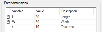
- Variable
- The first in the column is the check box related to locking.
- Default if Selected variable values only from list is not selected. In this case, when adding a feature or component, the values of the variables can be modified freely.
- Variable is locked.
- Variable not locked.
- Value
- Enter a variable value that is appropriate for the dimension table label.
- Description
- Enter a description for the variable.
- The description helps to understand the meaning of the variable.
- Components - Original Size
- This section appears only in the assembly dialog box Dimension Table.
- In the list, all the different and different-sized components in the assembly are detailed.
- The field is inactive
- Components - New Size
- This section appears only in the assembly dialog box Dimension Table
- Click on the row for the component to be replaced.
- Click the preset button
 in the New Size field.
- The program opens a list of available options.
- Select a new size from the list.
- Changeable Instances - Original
- This section is only visible in the Dimension Table dialog box of an assembly that is defined as a design automaton and has interchangeable parts or an assembly defined.
- This program shows the parts or assemblies that are interchangeable in the model.
- Define Assembly Properties
- Changeable Instances - New
- This section is only visible in the Dimension Table dialog box of an assembly that is defined as a design automaton and has interchangeable parts or an assembly defined.
-
- Click on the row for the instance to be replaced.
- Click on the preset button in the New field .
- The program opens a list of available options.
- Select a new instance from the list.
- Changeable Instances - Change Similar
- This section is only visible in the Dimension Table dialog box of an assembly that is defined as a design automaton and has interchangeable parts or an assembly defined.
- Apply
- Preview by clicking the Apply button in the dialog box. This will show you how the model would look if you confirm the function by clicking OK. If necessary, you can still edit the data.